4 cop connector p50(15), Table 3-14, Cop header (p50) – Artesyn MVME2502 Installation and Use (April 2015) User Manual
Page 75: Controls, leds, and connectors
Controls, LEDs, and Connectors
MVME2502 Installation and Use (6806800R96E)
75
3.4.2.4
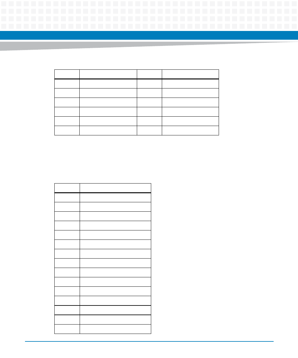
COP Connector P50(15)
The COP header is not populated by default.
49
SCAN 4 TCK 3
50
SCAN 4 TRST
51
SCAN 5 TMS
52
SCAN 5
53
SCAN 5 TDO
54
GND
55
+3.3V
56
SCAN5 TCK2
57
SCAN 5 TDI
58
GND
59
SCAN 5 TRST
60
NC
Table 3-13 JTAG Connector (P6) (continued)
Pin
Signal Description
Pin
Signal Description
Table 3-14 COP Header (P50)
Pin
Signal Description
1
JTAG TDO
2
COP QACK
3
JTAG TDI
4
COP TRST
5
COP RUNSTOP (Pulled UP)
6
COP VDD SENSE
7
JTAG TCK
8
COP CHECK STOP IN
9
JTAG TMS
10
NC
11
P2020 SW RESET
12
COP PRESENT
13
COP HARD RESET
14
KEYING
15
COP CHECK STOP OUT
This manual is related to the following products:
- MVME2502 Installation and Use (August 2014) MVME2500 Installation and Use Manual (February 2014) MVME2500 ECC Installation and Use (August 2014) MVME2500 Installation and Use (April 2015) MVME2500 Installation and Use Manual (March 2015) MVME2502 Installation and Use (April 2014) MVME2502 Installation and Use (December 2014)