10 pld u-boot and tsi monitor register, 11 pld boot bank register, Table 5-13 – Artesyn MVME2502 Installation and Use (April 2015) User Manual
Page 121: Pld u-boot and tsi monitor register, Table 5-14, Pld boot bank register
Memory Maps and Registers
MVME2502 Installation and Use (6806800R96E)
121
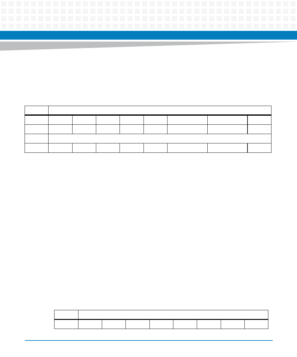
5.5.10 PLD U-Boot and TSI Monitor Register
The MVME2502 PLD provides an 8-bit register which indicates the status of the U-Boot's
normal environment switch and TSI interface signals.
5.5.11 PLD Boot Bank Register
The MVME2502 PLD provides an 8-bit register which is used to declare successful U-Boot
loading, indicating the SPI boot bank priority and actual SPI bank it booted from.
Table 5-13 PLD U-Boot and TSI Monitor Register
REG
PLD PCI_PMC_XMC_MNTR - 0xFFDF001E
Bit
7
6
5
4
3
2
1
0
Field
RSVD
RSVD
RSVD
RSVD
RSVD
BDFAIL_N
NORMAL_ENV
SCON
OPER
R
RESET
0
0
0
0
0
X
X
X
Field Description
BDFAIL_N
TSI148 BDFAIL_N Pin out
1 - No TSI Fail
0 - TSI Fail
NORMAL_ENV
Normal Environment Switch Indicator
1 - Use safe ENV
0 - Use normal ENV
SCON
System Controller Indicator
1 - System Controller
0 - Non-system Controller
Table 5-14 PLD Boot Bank Register
REG
PLD Boot Bank - 0xFFDF0050
Bit
7
6
5
4
3
2
1
0
- MVME2502 Installation and Use (August 2014) MVME2500 Installation and Use Manual (February 2014) MVME2500 ECC Installation and Use (August 2014) MVME2500 Installation and Use (April 2015) MVME2500 Installation and Use Manual (March 2015) MVME2502 Installation and Use (April 2014) MVME2502 Installation and Use (December 2014)