Toshiba – Toshiba LF600F User Manual
Page 30
Attention! The text in this document has been recognized automatically. To view the original document, you can use the "Original mode".
TOSHIBA
i6,F,8,A0,8,6,9,
LF602F
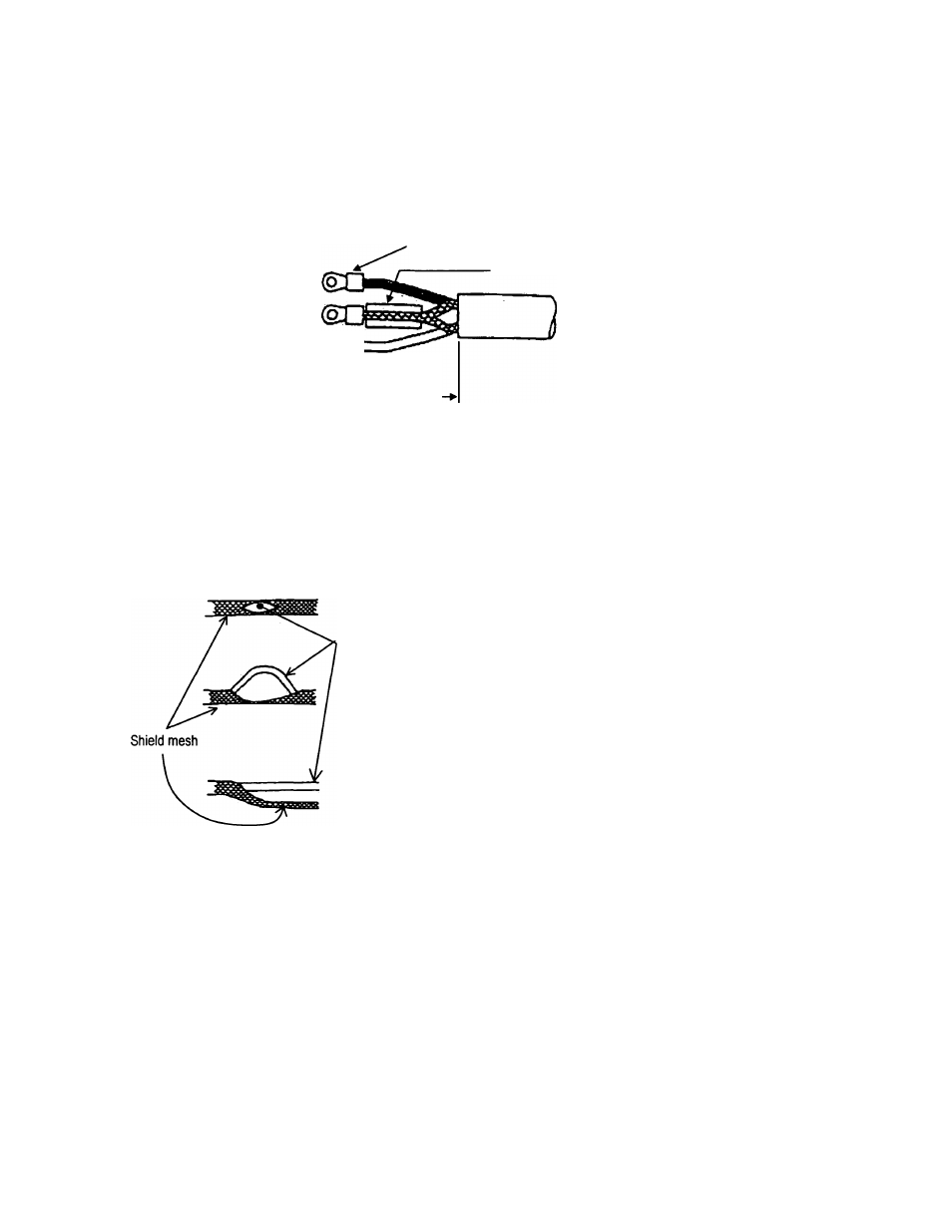
(3) Connecting the input signal cable:
Strip the sheath from the end of each conductor of a 2-core individually shielded cable as shown in
Figure 5.9. Twist those shields and cover them with a thermal contraction tube or vinyl tube not to
make contact with the case or core wires. Then attach an M3.5 crimping terminal with insulated
sleeve as shown in Figure 5.8. Connect a crimping terminal to the A and B terminals on the terminal
block and connect to each G terminal of the detector and converter.
A Black
G Shield
B White
(
q
^
,M3.5 crimping terminal
.Thermal contraction tube or vinyl tube
25~45mm
Figure 5.8 Terminal Treatment of Flow Rate Signal Cable
Notes on signal cable shield processing work
When stripping an external sheath, intermediate and insulated sheath, be careful not to scratch or
cut the internal conductors and shield mesh. Do not disjoint the shield mesh but treat it as shown in
Figure 5.9.
Coated wire
a.
Open the shield mesh with a pincette or the like.
b.
Pull out the internal coated wires from the hole of the
shielded mesh.
c.
Pull out all internal coated wires and extend the shield mesh wire.
Figure 5.9 Treating the Signal Cable Shield Mesh
-
29
-