Converter hardware failure, Toshiba – Toshiba LF600F User Manual
Page 142
Attention! The text in this document has been recognized automatically. To view the original document, you can use the "Original mode".
TOSHIBA
i6,F,8,A0,8,6,9,
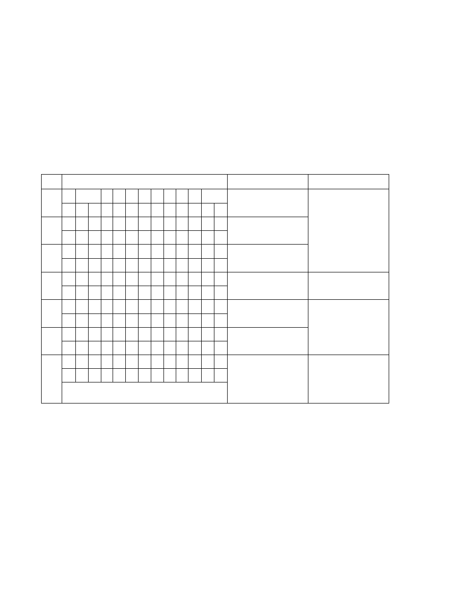
Converter hardware failure
The system checks the internal circuitry at the time of power-up for all error items and checks
continuously for the specified items as described below.
If an error is detected, one of the messages
shown in the table below will be displayed.
If multiple errors occur,
their messages will be displayed cyclically.
The diagnostics items
concerning the excitation cable and excitation circuit are detected using the ADC circuit.
Thus,
if the ADC fails (No.6), No. 4 (excitation cable) and No. 5 (excitation circuit) errors
cannot be detected correctly.
Further, this entire checking system is based on the CPU in the
flowmeter. Therefore,
if the CPU fails, no accurate diagnostics or error message display can be
obtained.
NO.
LCD display
Description
Corrective action
1
*
I
^
0
M
E
R
R
0
R
• I *
ROM error
Internal components or
printed-circuit board must
be repaired or replaced.
Contact you're nearest
Toshiba representative.
2
*
R
A
M
E
R
R
0
R
*
RAM error
3
P
A
R
A
M
E
T
E
R
System parameter error
F
A
I
L
U
R
E
4
E
X
C
U
R
R
E
N
T
Excitation cables are not
connected.
Connect the excitation
cables correctly.
0
P
E
N
5
E
X
C
U
R
R
E
N
T
An error occurred in the
excitation circuit.
Internal components or
printed-circuit board must
be repaired or replaced.
Contact you're nearest
Toshiba representative.
E
R
R
0
R
6
A
D
C
E
R
R
0
R
ADC error
7
I
N
V
A
L
I
D
Totaiizer data was
destroyed due to
external noise.
(No message appears if
totalization is not used.)
The error message
disappears if you press
the reset key.
T
0
T
A
L
Notes
1
.
Errors No. 1 to No. 3 can be detected
only at the time of power-on. The flowmeter does not
start measurement
if any one of these errors is detected. If these errors occur after power-on, the
flowmeter cannot detect these errors, and thus
may indicate and output incorrect data.
2.
Errors No.
4
to No.
6 may not be detected even if the errors result in incorrect flowmeter
accuracy, because of characteristic differences in components used to detect these errors.
3.
CPU error cannot be detected.
If the CPU stops, the watchdog timer resets the internal circuits
and the flowmeter starts again from the initial power-on condition. Depending on CPU condition,
the flowmeter
may not indicate and output correct data.
-
141
-