2 external device connections and grounding, 1 lf600f type, Toshiba – Toshiba LF600F User Manual
Page 24
Attention! The text in this document has been recognized automatically. To view the original document, you can use the "Original mode".
TOSHIBA
6,F,8.A0|8|6,9,
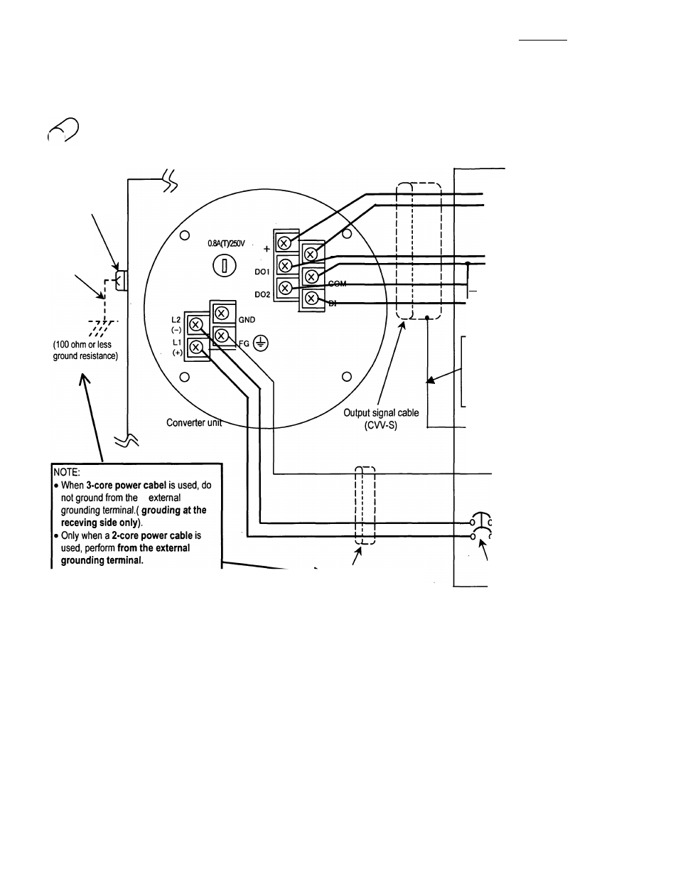
5.2 External Device Connections and Grounding
5.2.1 LF600F Type
&
LF600F
The terminal board connections of an integral type converter LF600F are shown in Figure 5.1.
Proceed with wiring as described in Section 5.4, “Wiring Procedure.”
[Instrumentation panel: Customer]
(Receiving side)
Ground terminal
IV wire
5.5mm^ or more
Power cable (CW)
* For a 2-core cable, L1
and L2 only.
Current output
(4-20mAdc)
or PROFIBUS
Digital output 1
Common for DI/DO
— Digital output 2
“ Digital input
(20to30Vdc)
NOTE:
To avoid 2-point grounding,
ground the shield of the output
cable basically at the receiving
side.
IW
(100 ohm or less
ground resistance)
(100 ohm or less
ground resistance)
Power supply
Wiring breaker
(double-pole/single-throw)
Figure 5.1 External Wiring Schematic Diagram
* Use a heavy copper braid or wire (cross-sectional area 5.5 mm^ minimum) to ground the
terminal and make it as short as possible as shown in Figure 5.1 for grounding.
Also, Avoid a common ground where earth current may flow. (An independent ground is
preferable.)
* The converter has no power switch. Install the power switch at the system side. Be sure to use a
double-pole/single-throw (both disconnection) wiring breaker.
-
23
-