Cub Cadet 6 x 4 Big Country User Manual
Page 98
Section 6: Front Suspension
6 - 3
6
2.7.
Pronounced tread wear at the inner edge of
either front tire indicates a negative camber con-
dition (leaning in at the top) at that wheel.
NOTE: If the Big Country is consistently oper-
ated with a heavy load, this may be normal wear
for the conditions.
NOTE: Mechanical causes of negative camber
include: weak or broken front springs, bent
steering knuckle, bent axle assembly, bent
spring mount.
NOTE: Worn wheel bearings or wear in the joint
where the steering knuckle meets the axle
assembly may cause apparent negative camber,
but the worn items must be repaired before cam-
ber evaluation is made.
2.8.
Pronounced tread wear at the outer edge of
either front tire indicates a positive camber con-
dition (leaning out at the top) at that wheel.
NOTE: Mechanical causes of positive camber
Include: bent steering knuckle, bent axle assem-
bly.
2.9.
Feathered edges on the tread blocks indicate a
toe angle issue. Proper alignment will correct
this condition.
NOTE: If the tread blocks appear smeared
(feathered) toward the outside edge of the tire, it
has toe-in (the front of the tires is closer together
than the back of the tires).
NOTE: If the tread blocks appear smeared
(feathered) toward the inside edge of the tire, it
has toe-out (the front of the tires is farther away
from each other than the back of the tires).
2.10. Scalloped tread indicates some form of oscilla-
tion while the tire is rotating. Mechanical sources
of this sort of problem would include: bent
wheels, a worn tie rod end, worn wheel bear-
ings, failed shock and spring unit, worn joint
between the steering knuckle and the axle
assembly, worn steering rack, bad tire.
2.11. Check the condition of the rubber bump stops
2.12. Place a block next to each front tire for sighting
purposes, and spin each tire. They should both
spin true to within 1/4” measured at the sidewall.
The bearings should spin quietly.
See Figure 2.12.
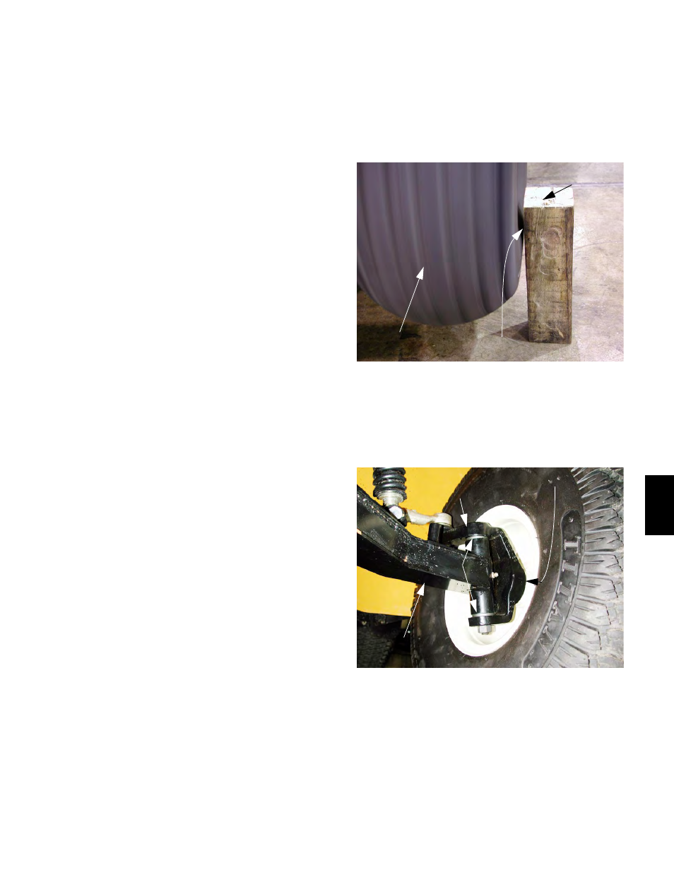
2.13. Grip the top and bottom of each front tire, and
attempt to rock it in a vertical plane. If more than
1/8” of play is present, identify the source of the
play. See Figure 2.13.
NOTE: The two greatest potential sources of
play are worn wheel bearings and worn compo-
nents at the joint between the steering knuckle
and the axle assembly (sleeve bushings, pivot
bolt, spacer).
Figure 2.12
Sighting Block
Spinning Tire
Watch Gap Here
Figure 2.13
Wheel Bearing Play Here
Axle Assembly
Steering Knuckle
Look For Play Here