Cub Cadet 6 x 4 Big Country User Manual
Page 81
Section 4: Engine and Transmission Support Asssembly
4 - 12
3.
Engine Support Assembly Isolator Mounts
(Rear), Removal and Replacement
3.1.
Position the Big Country on a firm level surface
in a location that leaves room to work around the
rear of the vehicle.
3.2.
Turn the engine off, remove the key, and set the
parking brake.
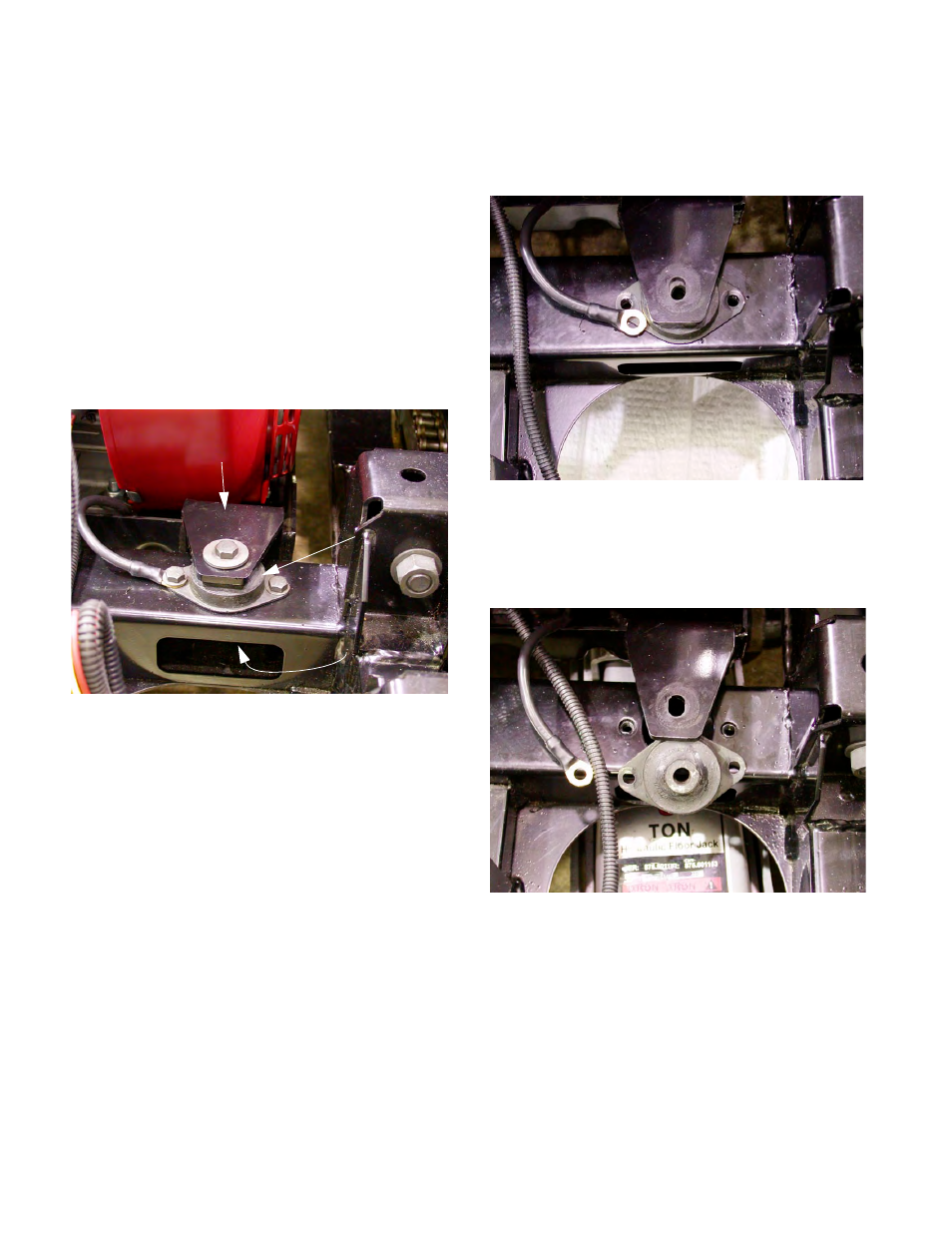
3.3.
Reaching in through the opening at the back of
the frame, insert a 9/16” wrench through the slot
in the back of the rear frame cross-member to
reach the nut on the bolt that holds the engine
and transmission support assembly to the isola-
tor mount. See Figure 3.3.
3.4.
Loosen the bolt using a second 9/16” wrench.
3.5.
Remove the nut and the large fender washer
from within the frame cross-member.
3.6.
Lift the bolt and heavy flat washer out of the iso-
lator and engine support assembly.
3.7.
Remove the two bolts that hold the isolator
mount to the frame using a ½” wrench.
See Figure 3.7.
3.8.
Use a jack to lift the engine support assembly far
enough (3/8”) to allow the isolator mount to slip
out of the frame cross-member. See Figure 3.8.
3.9.
To Install an Isolator Mount, reverse the steps
of the removal procedure.
3.10. Refer to the torque tabel at the back of this sec-
tion when tightening the fasteners.
NOTE: The ground cable from the engine to the
frame is secured under one of these isolator
bolts. It must have good electrical contact, or the
starter and charging system will not work prop-
erly.
Figure 3.3
Rear Mounting Point of Engine and
Transmission Support Assembly
Isolator Mount
Access to Nut
Figure 3.7
Figure 3.8