Cub Cadet 6 x 4 Big Country User Manual
Page 47
Section 3: Drive Axle Service
3 - 4
4.
Chain Tension Adjustment (Early units
Equipped With Fixed Chain Guides)
NOTE: Chains are used to transfer power from
each of the front drive axles to the rear drive
axles. The chains are set tight from the factory,
and will not reach normal operating length and
tension until the Big Country has been used.
NOTE: Early production Big Country vehicles
used adjustable lower chain guides to set chain
tension. Current production units use spring
loaded rotary arm tensioners with delrin rollers.
Refer to the section of this manual that covers
the applicable style of tensioner when servicing
the drive chains.
NOTE: The chain tension should be checked,
and adjusted if necessary every ten hours of
operation. When used in heavy load or abrasive
conditions they should be checked more fre-
quently. When used in light load conditions sev-
eral ten-hour intervals may pass before a chain
adjustment is needed.
NOTE: Each time the chain tension is checked,
the chain guides and sprockets should be given
a visual inspection.
4.1.
Lift and support the vehicle, according to the
directions in “Lifting the Big Country and Remov-
ing the Wheels”.
4.2.
Lift the bed.
4.3.
Allow the engine to cool if it has been run
recently.
4.4.
Rotate the drive wheels toward each other, so
that the slack in the chain falls between the top
of the two sprockets. See Figure 4.4.
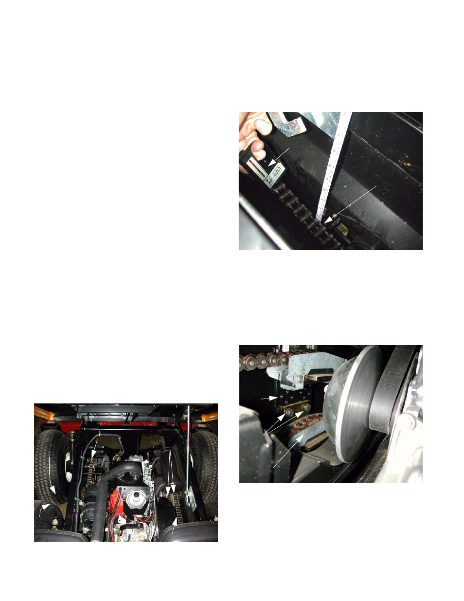
4.5.
Use a spring scale to apply a 5 lb. load to long-
est span in the chain between the sprocket and
the chain guide, at the top of the chain. The
chain should deflect between ½” and 1” at this
point. See Figure 4.5.
4.6.
If chain adjustment is necessary, use a 9/16”
wrench to remove the two bolts that hold the
lower chain guide to the frame.
4.7.
Lift the chain guide up to the highest set of holes
that can be reached without applying force to the
chain. See Figure 4.7.
4.8.
Install the bolts through the chain guide, and
tighten them using a 9/16” wrench.
Figure 4.4
Wheels
Rotate
Right Chain
Left Chain
Chain Guides
Figure 4.5
5 lb. Pull
1/2” to 1” Deflection
Figure 4.7
Lower Chain Guide
Mounting Bolts
Threaded
Adjustment
Holes