Rear sprocket removal and replacement – Cub Cadet 6 x 4 Big Country User Manual
Page 66
Section 3: Drive Axle Service
3 - 23
3
13.6. Examine the rubber travel stops while the axle
assembly is out. They can be replaced without
removing the axle assembly, but they are much
easier to reach with the axle removed.
13.7. To install the rear drive axle assembly, per-
form the following steps.
13.8. Apply a small amount of Benaline 920 to the
bolts that the axle assembly pivots on, keeping
the grease off of the threads that will be in con-
tact with the locking nut.
13.9. Apply a small amount of anti-seize compound to
the splines.
13.10.Position the axle assembly in the frame. Position
the drive sprocket on the axle as the axle is
pushed into place.
13.11. Insert the thrust washers between the axle
assembly and the mounting points on the frame.
13.12.Apply Loctite 242 or a similar thread locking
compound to the nuts that go on the bolts that
the axle pivots on.
13.13.Install the bolts, washers, and locking nuts.
13.14.Tighten the nuts to a torque of 175-195 ft-lb.
using a pair of 15/16” wrenches.
13.15.Secure the sprocket to the axle with a snap ring,
using a snap-ring tool.
13.16.Install the drive chain, following the instructions
given in the “Chain Removal and Replacement”
section of this manual.
13.17.Install the spring and shock assembly from the
axle assembly that is to be removed, following
the instructions given in the “Spring and Shock
Assembly Removal and Replacement” section of
this manual.
13.18.Connect the bed prop rod or the electric lift
motor by reversing the process by which it was
disconnected.
13.19.Install the wheel and lower the Big Country to
the ground, following the procedures described
in the “Lifting the Big Country and Removing the
Drive Wheel” section of this manual.
14.
Rear Sprocket Removal and Replacement
NOTE: The procedure for removing and replac-
ing the rear sprocket is identical to the procedure
for removing and replacing the rear drive axle as
described in the “Rear Drive Axle Removal and
Replacement” section.
15.
Axle Bushing Removal and Replacement
15.1. Remove the axle assembly as described in the
“Drive Axle Service: Front Drive Axle Removal
and Replacement” or “Rear Suspension Service:
Rear Drive Axle Removal and Replacement”
section of this manual.
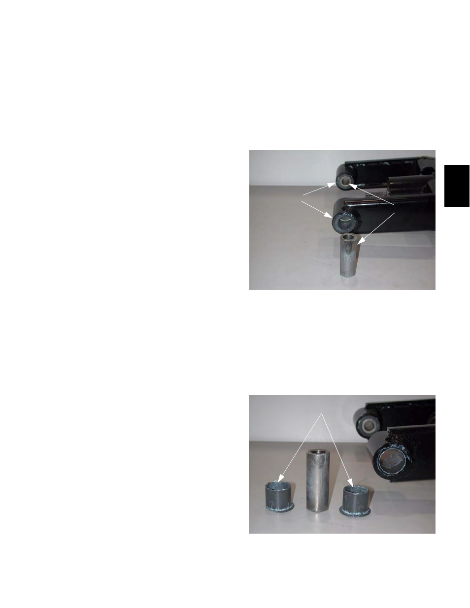
15.2. Push the metal sleeves out of the axle assembly
with light finger pressure. See Figure 15.2.
NOTE: The metal sleeves ride in shouldered
polymer sleeve bearings.
15.3. Drive the sleeve bearings out of the axle assem-
bly with a soft drift (brass, aluminum or wood), to
insure that no damage is done to the axle
assembly. The bearings will be destroyed in the
process. See Figure 15.3.
Figure 15.2
Metal Sleeves
Polymer Sleeve Bearings
Figure 15.3
Polymer Sleeve Bearings Removed