Shift linkage adjustment – Cub Cadet 6 x 4 Big Country User Manual
Page 12
Section 2: Clutch, Transmission, Brakes, Linkages
2- 3
2
2.13. Withdraw the pivot pin. See Figure 2.13.
2.14. Remove the shift lever.
2.15. Reverse the removal procedures to install
the shift linkage components.
NOTE: Apply white lithium grease to all pivot
points on assembly.
NOTE: Check shift linkage adjustment before
returning the unit to service.
3.
Shift Linkage Adjustment
3.1.
Perform steps 1 through 7 of the “Shift Linkage
Removal” section of this manual.
3.2.
Use a 9/16” wrench to loosen the jam nut that
locks the clevis on the end shift rod.
See Figure 3.2.
Pivot Pin
Figure 2.13
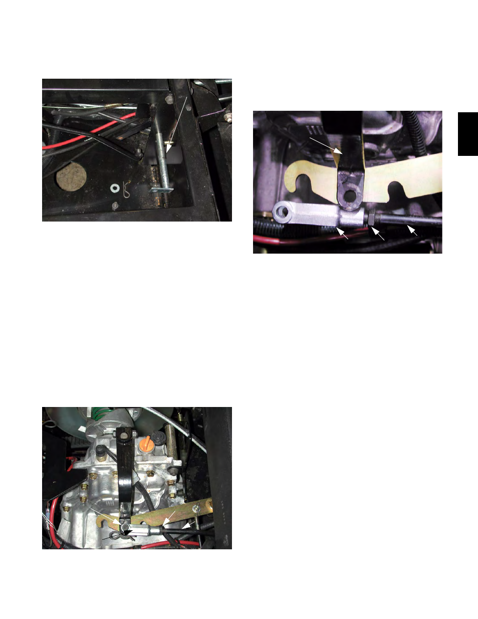
Figure 3.2
Shift rod
Jam Nut
Clevis
Clevis Pin
3.3.
Remove the hairpin clip and clevis pin that con-
nect the clevis to the transmission shift arm.
3.4.
Rotate the clevis to thread it up or down the
length of the shift link. See Figure 3.4.
3.5.
Check the position of the hole in the transmis-
sion lever in relation to the hole in the clevis with
the transmission and shift lever in forward gear
and reverse gear.
NOTE: Forward and Reverse are at the two
extreme ends of the shift lever’s travel. If they
are both correct, neutral will be correct as well.
3.6.
Connect the clevis to the transmission lever by
installing the clevis pin and hairpin clip.
3.7.
Tighten the jam nut using a 9/16” wrench, lock-
ing the adjustment.
3.8.
Test the function of the shift lever with the brake
pedal depressed.
NOTE: The lever should click firmly into each of
the three positions without hitting the end of its
travel.
NOTE: The travel of the shift lever should be
centered in the slot.
NOTE: If an extreme amount of adjustment is
necessary to center the gearshift lever, the link-
age may be damaged.
Figure 3.4
Shift Rod
Jam Nut
Clevis
Transmission Lever