Cub Cadet 6 x 4 Big Country User Manual
Page 60
Section 3: Drive Axle Service
3 - 17
3
11.
Universal Joint Removal and Replacement
11.1. Remove the front drive axle as described in the
“Front Drive Axle Removal and Replacement”
section.
11.2. Remove the front drive sprocket as described in
the “Front Drive Sprocket Removal and Replace-
ment” section.
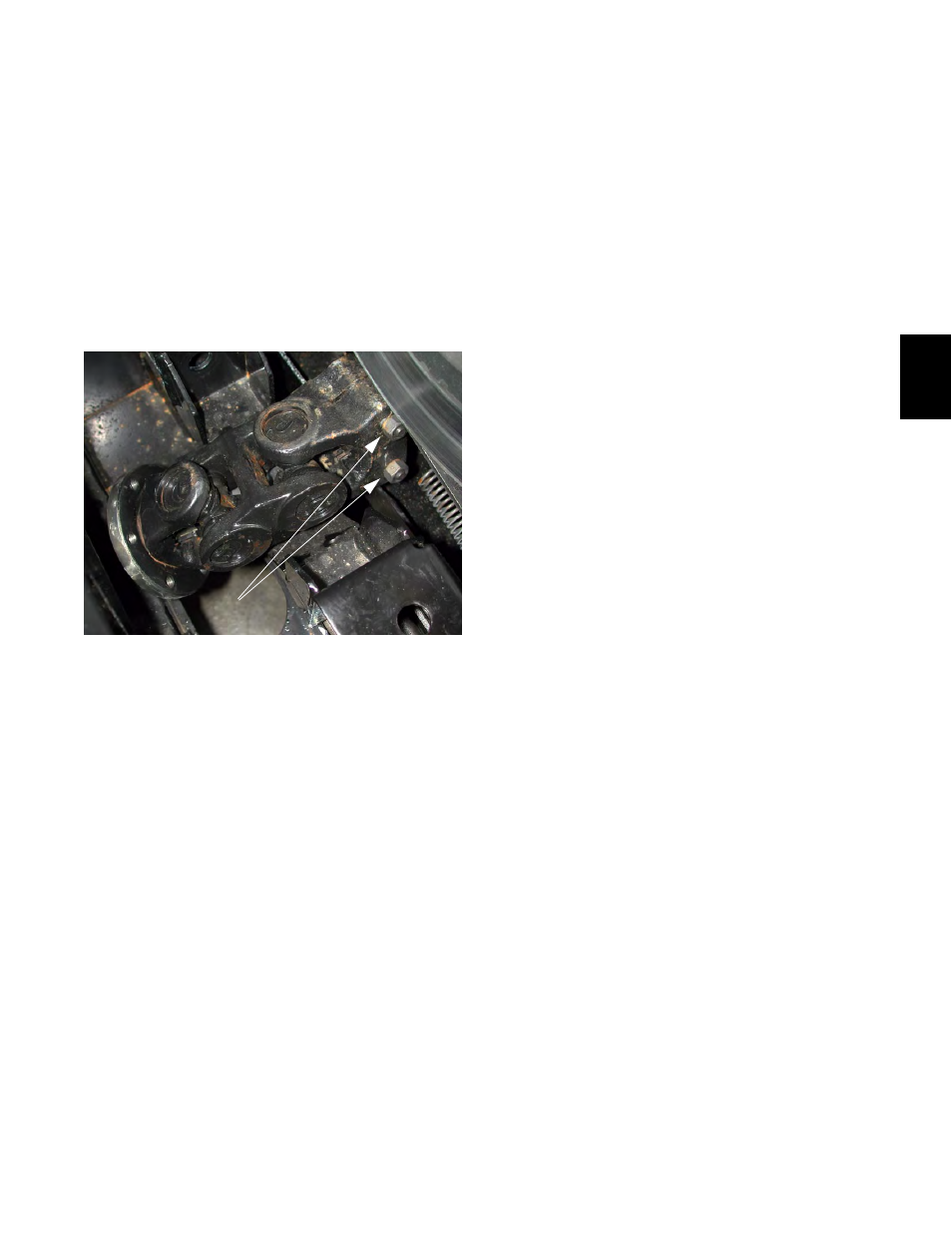
11.3. Loosen the two nuts that hold the pinch bolts in
the inner yoke of the universal joint.
See Figure 11.3.
11.4. Slide the universal joint off of the splined output
shaft from the transmission.
NOTE: The bolts do not pass through grooves in
the splined shaft, and need not be completely
removed.
NOTE: Each spline has the same pitch. The
shaft does not need to be indexed to the univer-
sal joint.
NOTE: Apply a small amount of anti-sieze com-
pound to the splines during assembly. The left
universal joint rides beneath the drive belt and
clutch. Centrifugal force will transfer grease to
these components during operation if too much
is applied.
11.5. Clean any rust or foreign material off of the mat-
ing surface of the sprocket and the flange that it
mounts to. Apply a small amount of anti-seize
compound to the mating surface.
11.6. To install a universal joint, slip it onto the
splined output shaft of the transmission, but do
not tighten the nuts on the pinch bolts at this
time.
Figure 11.3
Nuts on Universal Joint Pinch Bolts
11.7. Install the front drive sprocket to the universal
joint.
NOTE: The hole in the sprocket must align with
the grease zerk that feeds the spline.
11.8. Apply Loctite 242 or a similar thread locking
compound to the bolts that hold the sprocket to
the universal joint.
11.9. Using a 9/16” wrench, tighten the bolts as much
as possible.
NOTE: Tighten the bolts evenly, in a criss-cross
pattern, drawing the sprocket straight onto the
flange.
11.10. Lift the front drive axle assembly into position,
engaging the splines that connect the axle shaft
to the universal joint. Once in position, it will rest
on the bump stop until the bolts are installed.
11.11. Slip the thrust washers into place between the
axle assembly and the mounting points on the
frame.
11.12. Apply Loctite 242 or a similar thread locking
compound to the nuts that go on the bolts tat the
axle pivots on.
11.13. Apply a small amount of Benaline 920 to the
bolts that the axle assembly pivots on, keeping
the grease off of the threads that will be in con-
tact with the locking nut.
11.14. Install the bolts from the outside in. Install the
washers and locking nuts on the bolts. Tighten
them to a torque of 175-195 ft-lb. using a pair of
15/16” wrenches.
11.15. Tighten the bolts on the sprocket to a torque of
48-58 ft-lbs.
NOTE: apply and release the parking brake as
necessary to provide access to the bolts and
resistance to tighten against.
11.16. Insert the universal joint spacer tool (part num-
ber: 703-05104) in between the sprocket and the
circlip that holds the axle shaft and inner axle
bearing together.