Differential lock linkage removal and replacement – Cub Cadet 6 x 4 Big Country User Manual
Page 13
Section 2: Clutch, Transmission, Brakes, Linkages
2 - 4
NOTE: When the brake is released and a gear is
engaged, the pin that connects the clevis to the
transmission shift lever should be centered in a
slot in the interlock arm. If it is not, refer to the
“Shift Interlock and Clutch Brake Adjustment”
section of this manual.
NOTE: When the parking brake is set, the shift
lever should move between gears without catch-
ing or dragging against the interlock arm. If it
does not, refer to the “Shift Interlock Adjustment
and Clutch Brake Adjustment” section of this
manual.
4.
Checking Operation of the Differential Lock
Mechanism
4.1.
Lift and safely support the drive wheels of the
Big Country according to the procedures listed in
the “Lifting the Big Country and Removing the
Drive Wheels” section of this manual.
NOTE: Operation of the differential lock mecha-
nism may be tested by manually rotating the
drive wheels.
4.2.
With the differential lock released both drive
wheels on eather side of the vehicle should spin
when either the front or rear drive wheel is
rotated by hand. The drive wheels on the other
side of the Big Country should remain stationary.
4.3.
With the differential lock lever pulled-up roughly
half the length of the slot that it travels in, all four
wheels should rotate if any one wheel is turned
by hand.
4.4.
The differential lock should engage within 90
degrees of front drive wheel rotation.
4.5.
Once engaged, it will remain engaged even if
the lever is released, as long as there is a differ-
ence in the drive load between the left and right
sides of the vehicle.
NOTE: In service, differences in drive load
would result from greater traction on one side
than the other, attempting to turn the vehicle
while the differential lock is engaged, a dragging
brake on one side or the other, or grossly differ-
ent air pressures in the tires from one side to the
other.
4.6.
When the drive load is equalized from left to
right, the differential lock will automatically dis-
engage if the lever has been released.
NOTE: Internal transmission damage, or colli-
sion damage may result if the differential lock
lever is not operated in accordance with the
instructions in the “Big Country Operator’s Man-
ual”.
NOTE: It is normal for the steering abilities of
any six-wheeled vehicle to be greatly diminished
while the differential is locked.
NOTES
5.
Differential Lock Linkage Removal and
Replacement
5.1.
To reach the differential lock cable, Perform
steps 1 through 7 of the “Shift Linkage Removal”
section of this manual.
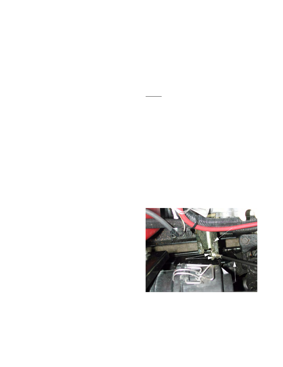
5.2.
To remove the cable, loosen the jam nuts that
hold the differential lock cable to the differential
lock bracket. See Figure 5.2.
NOTE: The differential lock bracket is located at
the right rear corner of the transmission, beneath
the air filter.
5.3.
Pull the cable housing out of the bracket.
Figure 5.2
Differential Lock cable
Jam Nuts
Differential Lock Bracket