Torque table: drive axle – Cub Cadet 6 x 4 Big Country User Manual
Page 69
Section 3: Drive Axle Service
3 - 26
16.9. Clean any paint or corrosion from the machined
recesses that the axle bearings fit into.
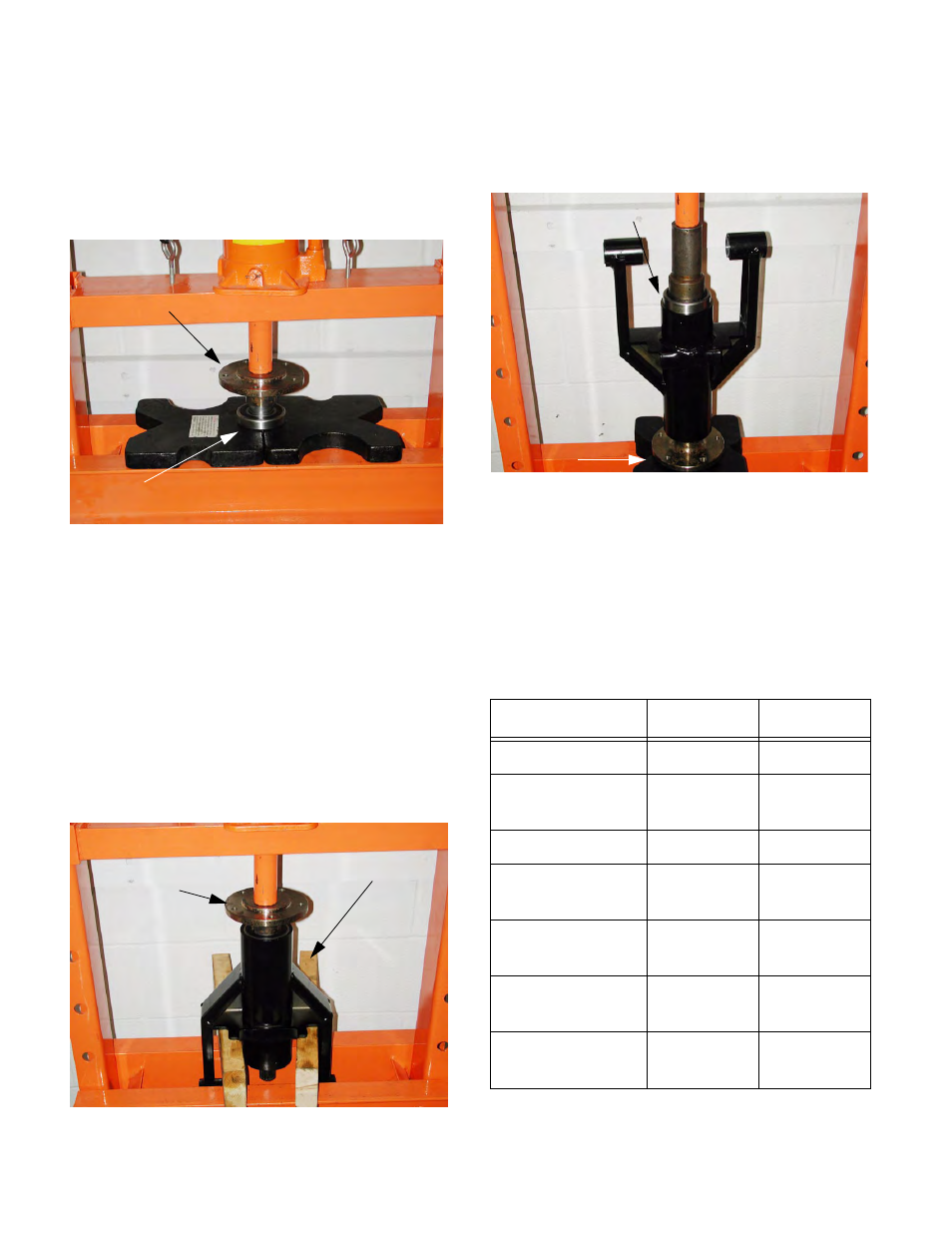
16.10.To put the drive axle assembly together, press
the outer axle bearing (larger internal diameter)
onto the axle shaft. See Figure 16.10.
NOTE: The press should be arranged to support
the bearing by the inner race, and press on the
axle shaft.
NOTE: The fit between the bearing and the axle
shaft is tighter than the fit between the bearing
and the axle weldment. Pressing the bearing
onto the shaft first allows the best control of the
pressing loads while assembling the pieces with
the tightest fit.
16.11. Press or drive the axle and outer bearing into the
axle weldment. See Figure 16.11.
16.12.Position the inner axle bearing over the splined
end of the axle and press it into place.
See Figure 16.12.
16.13.Slip the metal sleeves back into the bushings.
16.14.Install the axle assembly as described in the
“Front Drive Axle Removal and Replacement” or
“Rear Drive Axle Removal and Replacement”
section of this manual.
17.
Torque Table: Drive Axle
Figure 16.10
Support Inner Race of Bearing
Press Axle
Figure 16.11
Press Axle and Bearing
Support Weldment
Location
Inch-Lbs
Foot-Lbs.
Lug Bolts
75 ft-lbs
Spring and
Shock Unit
45-55 ft-lbs
Sprocket
48-58 ft-lbs
Drive Axle to
Vehicle
175-195
ft-lbs
Roller to Chain
Tensioner
45-55 ft-lbs
Chain Ten-
sioner to Vehicle
45-55 ft-lbs
Chain Ten-
sioner Index Bolt
110-120 in-
lbs
Figure 16.12
Support Axle
Press Bearing