Spring and shock assembly removal and replacement – Cub Cadet 6 x 4 Big Country User Manual
Page 54
Section 3: Drive Axle Service
3 - 11
3
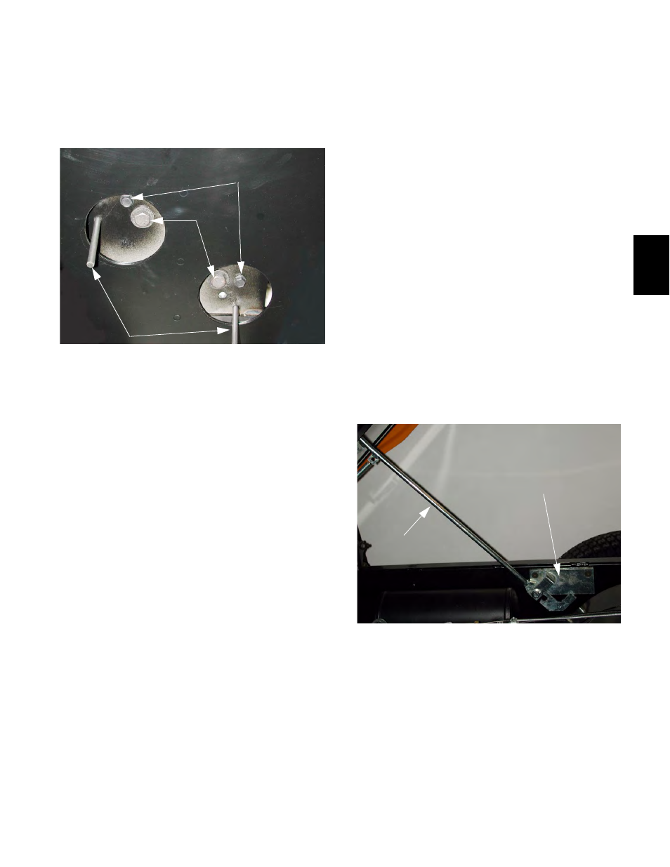
7.34. Push the upper tensioner arm down until the
locking hole in the arm aligns with the locking
hole in the frame, and insert the 1/4” steel lock-
ing pin to hold it in place. See Figure 7.34.
7.35. Install the chain as described in the “Chain
Removal and Replacement” section of this man-
ual.
NOTE: Chain tensioners will be found in place of
chain guides, but the procedure is otherwise
identical.
7.36. Press down on the lower chain tensioner arm,
withdraw the lock pin, and carefully release the
tensioner.
7.37. Press down on the upper chain tensioner arm,
withdraw the lock pin, and carefully release the
tensioner.
7.38. Position the air filter on the air intake shoulder,
and secure it there with the two bolts and wash-
ers previously removed.
7.39. Tighten the bolts using two 1/2” wrenches.
7.40. Remove the cover from the carburetor, and
install the hoses between the air filter, plenum,
and carburetor.
7.41. Tighten the hose clamps using a straight blade
screwdriver or a 5/16 driver.
NOTE: The hose that connects to the air horn of
the carburetor must be fully seated, and should
not come in contact with the bed when the bed is
in the lowered position.
7.42. Lower the bed, place the Big country on the
ground, and test the operation of the vehicle.
Figure 7.34
Locking Pins
Indexing Bolts
Mounting
Bolts
8.
Spring and Shock Assembly Removal and
Replacement
8.1.
Perform the steps described in the “Lifting Big
Country and Removing Tires” section of this
manual.
NOTE: If a spring and shock assembly is being
removed so that an axle assembly that does not
require service can be removed, it is not neces-
sary to disconnect the bottom of the spring and
shock unit. It may be left connected to the axle
assembly, and be removed along with it. An
example of this situation would be if the axle
must be removed to provide clearance to
remove a transmission that needs service.
NOTE: If a spring and shock assembly is to be
removed from a rear drive axle, it is necessary to
disconnect the prop rod that holds the bed in the
raised position (manual bed lift) or disconnect
the lift motor from the bed (electric lift).
8.2.
To disconnect the prop rod from the bracket
that holds it to the frame, loosen the socket head
cap screw at the front of the bracket three turns
using a 3/16” allen wrench. See Figure 8.2.
8.3.
Remove the socket head cap screw at the rear
of the bracket using a 3/16” allen wrench.
8.4.
Position an auxiliary prop rod (a length of 2 X 4
lumber will do), or a safety strap to prevent the
bed from lowering unexpectedly.
Figure 8.2
Prop Rod
Prop Rod Bracket