Bio-Rad BioLogic Signal Import Module (SIM) User Manual
Page 98
6.
Plumbing the AVR7-3 Inject Valve.
a. The inject port assembly and needle are included with each AVR7-3 inject valve. Screw this
assembly into port 2 of the valve until it is secure.
b. Connect the sample loop to ports 3 and 6.
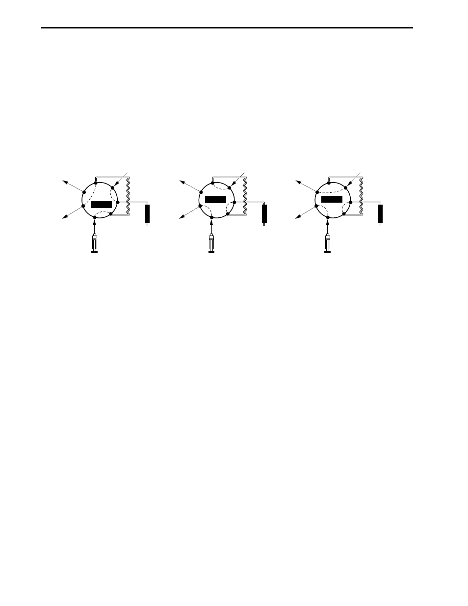
c. Plumb the inject valve according to Figure 4-6. Use the tubes labeled "waste" or make fittings
using 1/16” (1.6 mm) OD Tefzel tubing and 1/4-28 fittings for waste lines 1 and 7.
d. Use the tube labeled #3 or make a fitting using 1/16" (1.6 mm) OD Tefzel tubing and 1/4-28
fitting to go from port 4 to the column.
Figure 4-6. Inject Valve Plumbing for an AVR7-3
7.
Plumbing the UV Detector and Conductivity Monitor.
a. Connect a piece of 1/16” (1.6 mm) OD orange PEEK tubing (tube #4 in the tubing kit) between
the column outlet and the bottom inlet of the UV detector flow cell using 1/4-28 fittings. If you
are using the QuadTec detector, connect it to the flow cell which is bidirectional, using 10-32
fittings provided with the QuadTec.
b. Use the tube labeled #5 in the tubing kit or cCut approximately 8 cm of 1/16” (1.6 mm) OD
orange PEEK tubing and attach 1/4-28 fittings. Connect one end into the top of the UV detector
flow cell. Connect the other end into the Conductivity monitor flow cell which is bi-directional. If
you are using a QuadTec detector, connect tubing from its flow cell outlet using a 10-32 fitting to
either port of the Conductivity monitor using 1/4-28 fittings.
c. Place the Conductivity flow cell into the notch of the optics bench. This is a gentle push-fit.
There is a tag (with a number) attached to the conductivity cable. This number is the flow cell
constant and must be entered in the software before beginning a run. Refer to Table 5-6, page
5-10 Utilities drop-down Menu: Conductivity Flow Cell Constant Calibration.
d. For flow rates below 10 ml/min, insert the 40 psi backpressure regulator after the conductivity
monitor. Plumb the backpressure regulator following the direction of the arrow.
COLUMN
WORKSTATION
PUMP
SAMPLE
LOOP
SAMPLE
INJECT
WASTE
WASTE
6
7
1
2
3
4
5
LOAD
COLUMN
WORKSTATION
PUMP
SAMPLE
LOOP
SAMPLE
INJECT
WASTE
WASTE
6
7
1
2
3
4
5
INJECT
COLUMN
WORKSTATION
PUMP
SAMPLE
LOOP
SAMPLE
INJECT
WASTE
WASTE
6
7
1
2
3
4
5
PURGE
SYSTEM PLUMBING
SYSTEM INSTALLATION AND SETUP
4-6
- BioLogic DuoFlow Pathfinder 80 System DuoFlow™ Chromatography System BioLogic DuoFlow Pathfinder 20 System DuoFlow™ Chromatography System BioLogic DuoFlow Maximizer 80 System DuoFlow™ Chromatography System BioLogic DuoFlow Maximizer 20 System DuoFlow™ Chromatography System BioLogic DuoFlow QuadTec 40 System DuoFlow™ Chromatography System BioLogic DuoFlow QuadTec 10 System DuoFlow™ Chromatography System BioLogic DuoFlow 40 System Chromatography System BioLogic DuoFlow 10 System Chromatography System