Bio-Rad BioLogic Signal Import Module (SIM) User Manual
Page 77
SYSTEM SETUP
SYSTEM INSTALLATION AND SETUP
3-5
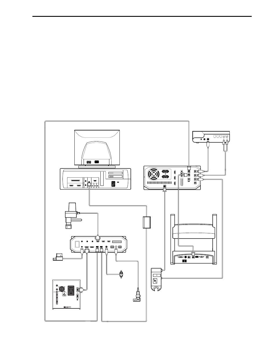
3.3.2 Systems with a Maximizer
If the Maximizer is to be part of the system, follow the procedure below to connect the Maximizer to the
Workstation and the USB Bitbus Communicator.
1.
Place the Workstation on top of the Maximizer.
2.
Note the two connectors marked “Instr Bus.” These connectors are identical: either may be used
when connecting instrument bus cables.
3.
With the back side of the Workstation and Maximizer facing you, connect System Cable 30
between the Workstation and the Maximizer.
4.
Select a System Cable of sufficient length to reach the USB Bitbus Communicator. System Cables
17, 18, 19, 21, and 30 are different only in their lengths.
5.
Connect the power cable to the Maximizer. Do not turn on this device yet.
Figure 3-5. System Cable Connections (with Maximizer)
BIOFRAC
WORKSTATION
SYSTEM CABLE 30
SYSTEM
CABLE 31
SYSTEM CABLE
17, 18, 19, OR 21
SYSTEM
CABLE 25
CONDUCTIVITY
MONITOR
SYSTEM CABLE
17, 18, 19, 21, OR 30
AVR7-3
INJECT
VALVE
MODEL 1327
CHART RECORDER
SYSTEM
CABLE 2
SYSTEM
CABLE 4
MAXIMIZER
pH MONITOR
MAXIMIZER
MIXER
QUADTEC
DETECTOR
DELL CONTROLLER
USB BITBUS
COMMUNICATOR
UV DETECTOR
- BioLogic DuoFlow Pathfinder 80 System DuoFlow™ Chromatography System BioLogic DuoFlow Pathfinder 20 System DuoFlow™ Chromatography System BioLogic DuoFlow Maximizer 80 System DuoFlow™ Chromatography System BioLogic DuoFlow Maximizer 20 System DuoFlow™ Chromatography System BioLogic DuoFlow QuadTec 40 System DuoFlow™ Chromatography System BioLogic DuoFlow QuadTec 10 System DuoFlow™ Chromatography System BioLogic DuoFlow 40 System Chromatography System BioLogic DuoFlow 10 System Chromatography System