Bio-Rad BioLogic Signal Import Module (SIM) User Manual
Page 25
DESCRIPTION OF BIOLOGIC DUOFLOW SYSTEM
SYSTEM OVERVIEW
2-12
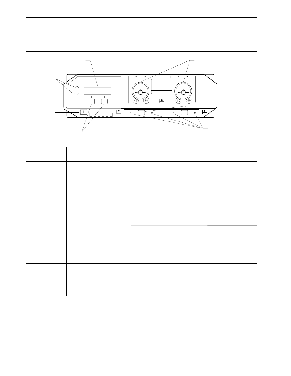
Table 2-7.
Maximizer Front Panel Controls
Description
Controls power to the unit.
Proportioning valves used for Buffer Blending and inlet selection. Each valve has
two inlet ports and one outlet port. For Buffer Blending, acid is placed at inlet A1,
base at inlet A2, water at inlet B1 and salt and inlet B2. The valve outlet ports are
connected directly to their respective Workstation pump inlet ports. Color-coded
tubing is supplied with the Maximizer for plumbing the inlet ports (A1 = red, A2 =
blue, B1 = yellow and B2 = green).
Used when the Maximizer is in Local mode to change the position of valves A and B.
Indicates which valve port is open.
Displays the Maximizer status. When the Maximizer is operated from its front panel
controls, the LCD displays status and control information, including valve positions, pH
and conductivity calibration information, and current temperature.
VALVE A
A1
ACID
A2
BASE
B1
WATER
B2
SALT
VALVE B
VALVES A & B
ARROW
KEYS
VALVE
INLET
SELECT
BUTTONS
SOFT KEYS
VALVE INLET
STATUS LEDs
LCD DISPLAY
ENTER
KEY
POWER
ON/OFF
Feature
Power On/Off
Valves A & B
Valve Inlet
Select Buttons
Valve Inlet
Status LEDs
LCD Display
- BioLogic DuoFlow Pathfinder 80 System DuoFlow™ Chromatography System BioLogic DuoFlow Pathfinder 20 System DuoFlow™ Chromatography System BioLogic DuoFlow Maximizer 80 System DuoFlow™ Chromatography System BioLogic DuoFlow Maximizer 20 System DuoFlow™ Chromatography System BioLogic DuoFlow QuadTec 40 System DuoFlow™ Chromatography System BioLogic DuoFlow QuadTec 10 System DuoFlow™ Chromatography System BioLogic DuoFlow 40 System Chromatography System BioLogic DuoFlow 10 System Chromatography System