Bio-Rad BioLogic Signal Import Module (SIM) User Manual
Page 43
Position 1 on the AVR9-8 is the default position when the system is powered up or at the end of a
method run unless configured differently from the Edit User Preferences window, available from the
Options menu.
The valve uses 1/4-28 fittings and 1/16” (1.6 mm) OD PEEK tubing supplied with the fitting kit
when plumbing these valves.
Connect the AVR9-8 valve signal cable to any of the available automated valve connectors on the
back of the Workstation (ports 4, 5, or 6). If a Maximizer is in use connect to ports 7, 8, or 9 before
those on the Workstation. If more than three valves are desired, you may connect additional valves
to ports 4, 5, and 6 on the Workstation. All valves will be active.
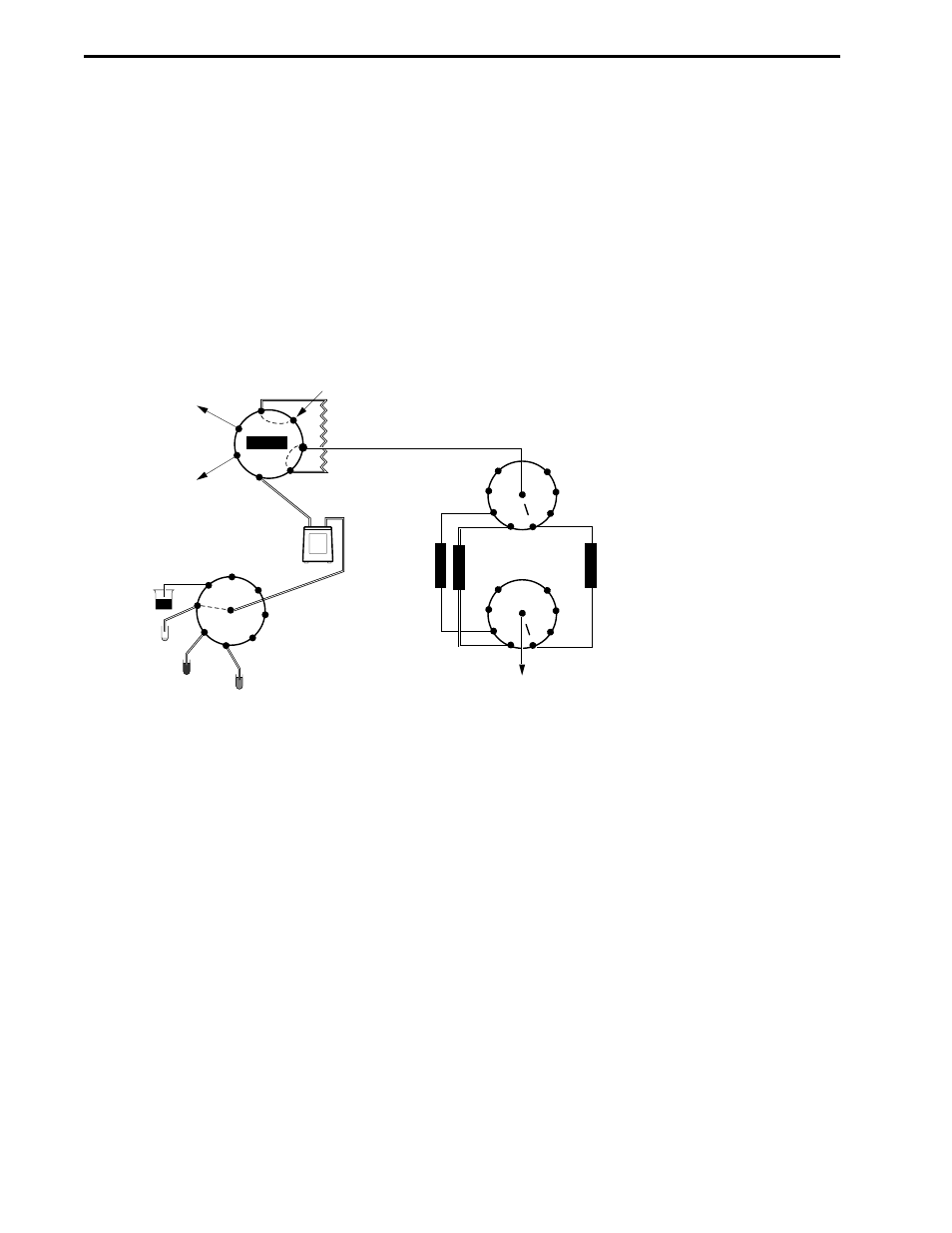
Figure 2-14. Two Examples Using AVR9-8 Valves
UV MONITOR &
FRACTION COLLECTOR
AVR9-8 AS COLUMN
SWITCHING VALVE
TO RECEIVE SAMPLE
AVR7-3 INJECT VALVE FOR SAMPLE APPLICATION
AVR9-8 FOR LOADING MULTIPLE SAMPLES
TWO AVR9-8 VALVES FOR
COLUMN SWITCHING
COLUMN INLET
SECOND AVR9-8 AS
COLUMN SWITCHING VALVE
TO DIRECT ELUENT,
TO MONITORS AND
FRACTION COLLECTOR
COLUMN OUTLET
5
4
3
2
1
7
6
9
UP TO 8
DIFFERENT
COLUMNS
8
5
4
3
2
1
7
6
9
8
COLUMN
WORKSTATION
PUMP
SAMPLE
LOOP
WASTE
WASTE
6
7
1
2
3
4
5
INJECT
1
2
3
4
5
6
9
7
8
RINSE
SAMPLE #1
SAMPLE #2
SAMPLE #3
AUX
PUMP
DESCRIPTION OF BIOLOGIC DUOFLOW SYSTEM
SYSTEM OVERVIEW
2-30
- BioLogic DuoFlow Pathfinder 80 System DuoFlow™ Chromatography System BioLogic DuoFlow Pathfinder 20 System DuoFlow™ Chromatography System BioLogic DuoFlow Maximizer 80 System DuoFlow™ Chromatography System BioLogic DuoFlow Maximizer 20 System DuoFlow™ Chromatography System BioLogic DuoFlow QuadTec 40 System DuoFlow™ Chromatography System BioLogic DuoFlow QuadTec 10 System DuoFlow™ Chromatography System BioLogic DuoFlow 40 System Chromatography System BioLogic DuoFlow 10 System Chromatography System