Bio-Rad BioLogic Signal Import Module (SIM) User Manual
Page 23
DESCRIPTION OF BIOLOGIC DUOFLOW SYSTEM
SYSTEM OVERVIEW
2-10
Table 2-6. (continued)
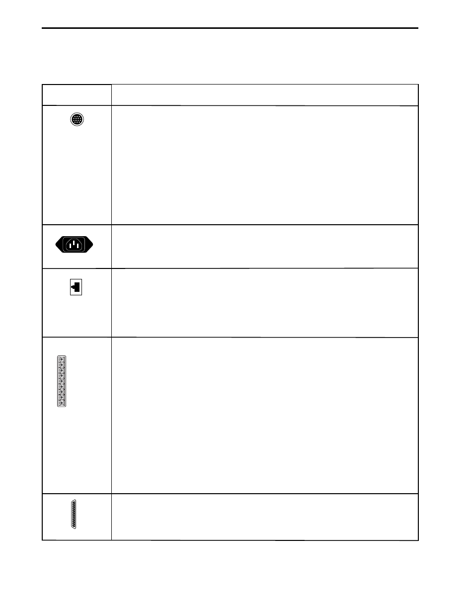
Workstation Rear Panel Connectors
Description
UV Chart: For UV signal output to a single or dual pen chart recorder. When the
Bio-Rad Model 1327 is used, chart recorder Pen Up/Down, Stop/Start commands,
and event marks are sent from this connector.
The Bio-Rad Model 1327 dual pen recorder needs an 8-pin mini-DIN to standard DIN
cable (System Cable 2) and a mini-DIN to banana plugs cable (System Cable 4).
Generic chart recorders require an 8-pin mini-DIN to breakout cable (System Cable 7),
available from Bio-Rad.
When a Signal Import Module signal replaces the standard BioLogic UV Detector,
use System Cable 20 to control a Bio-Rad Model 1327 dual pen chart recorder.
The chart recorder should be set to 1V.
Power Cord: The grounded 3-prong connector inputs power to the Workstation
and outputs power to any unit connected to the Workstation. The Workstation’s
input power cord should be plugged into a 3-prong grounded power outlet.
Instr Bus: The RJ-45 modular phone connectors and the bus communication cables
connect the Workstation to the other components in the system. The Instrument Bus
handles all communications between the Controller and each of the components in
the system. For example, the Instrument Bus connects the Workstation to the USB
Bitbus Communicator, Maximizer, BioFrac fraction collector, or Econo Gradient
Pump. Components can be connected to the system in any order.
Aux: The 9-pin AUX PORT connects a variety of peripheral modules that cannot
communicate with the DuoFlow Controller over the Instrument Bus. If the Maximizer
is being used, use its AUX connector before the connector on the Workstation.
Pin #
Description
1
Inject. A contact closure between pins 1 and 9 (GND) satisfies a Hold
command which has been programmed in a method protocol.
2
n/c. No connection
3
n/c. No connection
4
n/c. No connection
5
FC Adv. Model 2110 and generic fraction collector Advance output.
6
AUX Pump. A Stop-Start command is sent to a pump (e.g., Bio-Rad EP-1).
7
n/c. No connection
8
n/c. No connection
9
GND. Ground
Reserved for internal Bio-Rad use.
Conector
1 INJECT
2 N/C
3 N/C
4 N/C
5 FC ADV
6 AUX PUMP
7 N/C
8 N/C
9 GND
AUX PORT
- BioLogic DuoFlow Pathfinder 80 System DuoFlow™ Chromatography System BioLogic DuoFlow Pathfinder 20 System DuoFlow™ Chromatography System BioLogic DuoFlow Maximizer 80 System DuoFlow™ Chromatography System BioLogic DuoFlow Maximizer 20 System DuoFlow™ Chromatography System BioLogic DuoFlow QuadTec 40 System DuoFlow™ Chromatography System BioLogic DuoFlow QuadTec 10 System DuoFlow™ Chromatography System BioLogic DuoFlow 40 System Chromatography System BioLogic DuoFlow 10 System Chromatography System