Bio-Rad BioLogic Signal Import Module (SIM) User Manual
Page 17
DESCRIPTION OF BIOLOGIC DUOFLOW SYSTEM
SYSTEM OVERVIEW
2-4
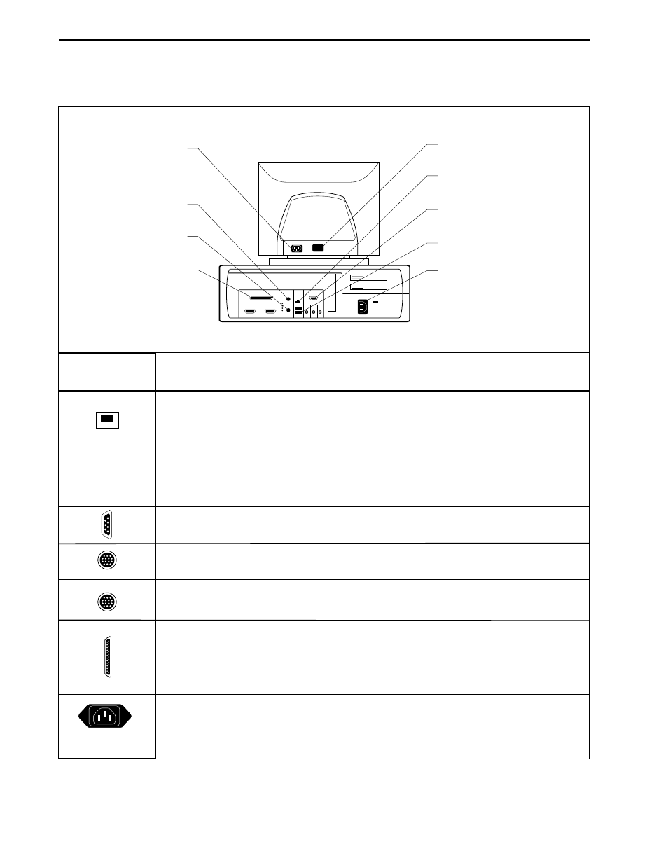
Table 2-2.
Rear View of the Dell PC Computer as the DuoFlow Controller
Description
USB connectors: These connect to the USB Bitbus Communicator, which in turn
connects to the instrument bus, and allows components of the BioLogic DuoFlow
system to communicate with the Controller. Components connect to the instrument
bus in a “daisy-chain” and are recognized when the system is switched on. Even
when one component is switched off, other components “daisy-chained” to the system
can be controlled by the Controller.
Monitor connector: To connect the color monitor to the Controller.
Keyboard connector: To connect the keyboard to the Controller.
Mouse connector: To connect the mouse to the Controller.
Parallel connector: Devices designed for connection to the parallel port include
printers and external storage devices. Refer to Windows
®
2000 and/or the device
documentation for installation instructions. (Some printer drivers are pre-installed on
the Controller.)
Power connectors: To connect the power cable.
DELL CONTROLLER
MOUSE
CONNECTOR
COLOR MONITOR
CONNECTOR
MONITOR POWER
CONNECTOR
ETHERNET
CONNECTOR
MONITOR
SIGNAL CABLE
USB BUS CONNECTORS
CONTROLLER
POWER CONNECTOR
KEYBOARD
CONNECTOR
PARALLEL
CONNECTOR
Connector
- BioLogic DuoFlow Pathfinder 80 System DuoFlow™ Chromatography System BioLogic DuoFlow Pathfinder 20 System DuoFlow™ Chromatography System BioLogic DuoFlow Maximizer 80 System DuoFlow™ Chromatography System BioLogic DuoFlow Maximizer 20 System DuoFlow™ Chromatography System BioLogic DuoFlow QuadTec 40 System DuoFlow™ Chromatography System BioLogic DuoFlow QuadTec 10 System DuoFlow™ Chromatography System BioLogic DuoFlow 40 System Chromatography System BioLogic DuoFlow 10 System Chromatography System