Bio-Rad BioLogic Signal Import Module (SIM) User Manual
Page 40
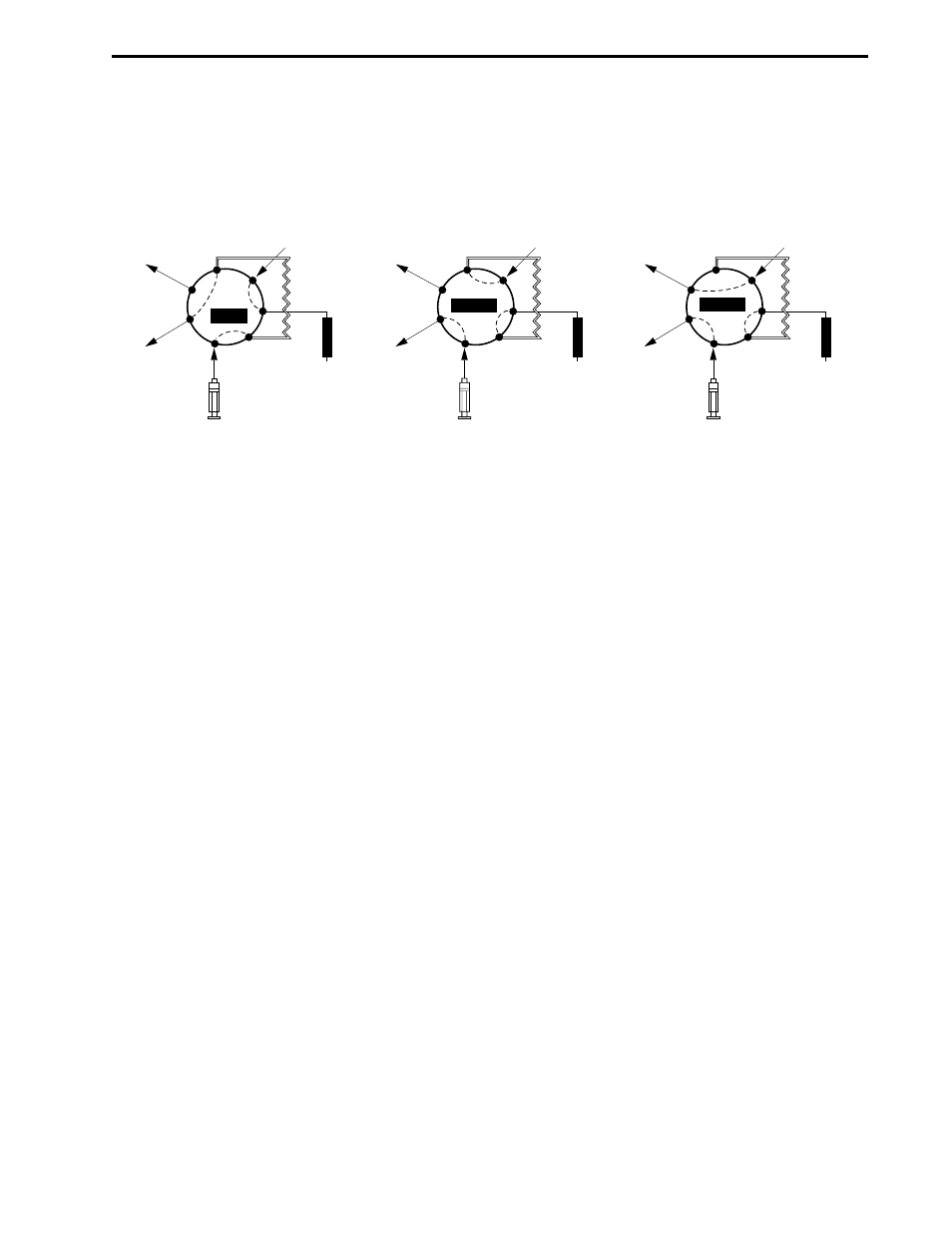
The three valve positions are Load (position 1), Inject (position 2), and Purge (position 3). See Figure 2-11.
Load is the default position when the system is powered up or at the end of a method run unless configured
differently from the Edit User Preferences window, available from the Options menu in the system software.
Figure 2-11. Sample Load Positions
The valve uses 1/16” (1.6 mm) OD tubing and 1/4-28 fittings. Sample loop sizes are available from 50 µl
loop (in the Starter kit included with all systems) to a maximum of 5 ml PEEK loop. Larger volume injections
may be obtained using Dynaloops, additional valves and/or an auxiliary pump.
Connect the AVR7-3 valve signal cable to any of the available Automated Valve connectors on the back of
the Workstation (ports 4, 5, or 6). If a Maximizer is in use connect to ports 7, 8, or 9 before those on the
Workstation. If more than 3 valves are desired, you may connect additional. valves to ports 4, 5, and 6 on
the Workstation. All valves will be active.
COLUMN
WORKSTATION
PUMP
SAMPLE
LOOP
SAMPLE
INJECT
WASTE
WASTE
6
7
1
2
3
4
5
LOAD
COLUMN
WORKSTATION
PUMP
SAMPLE
LOOP
SAMPLE
INJECT
WASTE
WASTE
6
7
1
2
3
4
5
INJECT
COLUMN
WORKSTATION
PUMP
SAMPLE
LOOP
SAMPLE
INJECT
WASTE
WASTE
6
7
1
2
3
4
5
PURGE
DESCRIPTION OF BIOLOGIC DUOFLOW SYSTEM
SYSTEM OVERVIEW
2-27
- BioLogic DuoFlow Pathfinder 80 System DuoFlow™ Chromatography System BioLogic DuoFlow Pathfinder 20 System DuoFlow™ Chromatography System BioLogic DuoFlow Maximizer 80 System DuoFlow™ Chromatography System BioLogic DuoFlow Maximizer 20 System DuoFlow™ Chromatography System BioLogic DuoFlow QuadTec 40 System DuoFlow™ Chromatography System BioLogic DuoFlow QuadTec 10 System DuoFlow™ Chromatography System BioLogic DuoFlow 40 System Chromatography System BioLogic DuoFlow 10 System Chromatography System