Bio-Rad BioLogic Signal Import Module (SIM) User Manual
Page 29
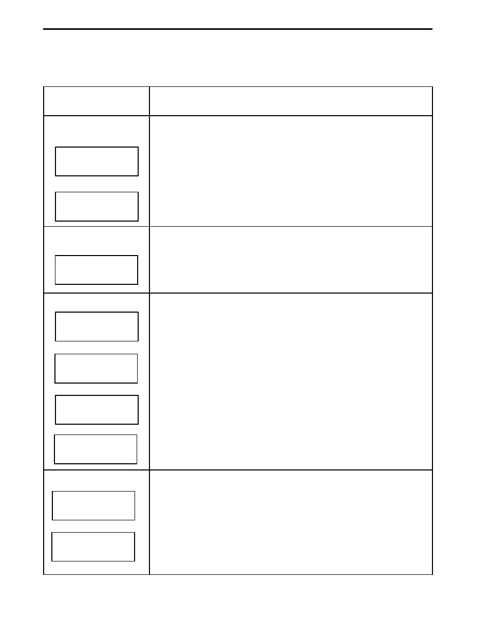
Table 2-9.
Maximizer Screens
Function and Description on Maximizer Faceplate in Local Mode
Inlet Selection
Arrow buttons switch between Inlets A1(0) and A2(1).
PREV changes to previous screen.
NEXT changes to next screen.
Arrow buttons switch between Inlets B1(0) and B2(1).
Valve Control
Arrow buttons select a port
may be displayed including three motorized (AVR7-3, AVR9-8) and three
solenoid (SVT3-2, SV5-4) valves.
ENTER accepts the change and moves the valve to the new position.
SIM Calibration
Displays the current Maximizer SIM voltage.
Used in conjunction with a 1 Volt calibration source.
Pressing ENTER sets the current voltage reading to 1 V.
Pressing the UP arrow resets the calibration to the factory setting.
After ENTER is pressed, the display responds with “SET” to show that the
calibration was successful.
After the UP arrow is pressed, the display responds with “RESET” to
show that the calibration was reset.
pH Calibration
Displays the current pH and temperature.
ENTER causes the Maximizer to enter pH calibration mode.
DESCRIPTION OF BIOLOGIC DUOFLOW SYSTEM
SYSTEM OVERVIEW
2-16
Screen
CAL pH?
PREV
ENTER = Y
NEXT
pH 6.00
PREV
22.6 C
NEXT
CAL SIM?
PREV reset
ENT=SET
NEXT
CAL SIM?
PREV set
ENT=SET
NEXT
CAL SIM?
PREV
ENT=SET
NEXT
SIM 0.000
PREV
Volts
NEXT
PREV
POS 0
NEXT
BLEND B
PREV
POS 1
NEXT
BLEND A
PREV
POS 0
NEXT
- BioLogic DuoFlow Pathfinder 80 System DuoFlow™ Chromatography System BioLogic DuoFlow Pathfinder 20 System DuoFlow™ Chromatography System BioLogic DuoFlow Maximizer 80 System DuoFlow™ Chromatography System BioLogic DuoFlow Maximizer 20 System DuoFlow™ Chromatography System BioLogic DuoFlow QuadTec 40 System DuoFlow™ Chromatography System BioLogic DuoFlow QuadTec 10 System DuoFlow™ Chromatography System BioLogic DuoFlow 40 System Chromatography System BioLogic DuoFlow 10 System Chromatography System