Parameters of the, Standard device of the industrial pc, Industrial pc | parameter setting & configuration – Lenze PC-based Automation Industrial PC User Manual
Page 51
2.5 EN - 01/2012
L
51
Industrial PC | Parameter setting & configuration
Web-based parameterisation with »WebConfig«
User interface
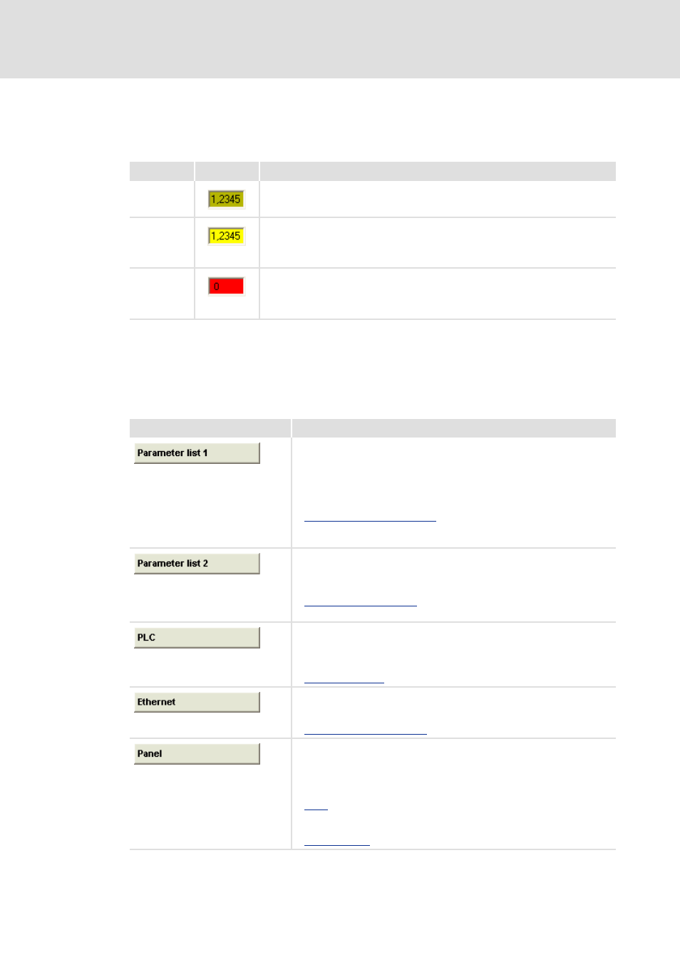
Representation of parameter values
In the display area of the web-based parameterisation, settings of device parameters are
represented with different background colours which have the following meaning:
In the following the individual menus of the web-based parameterisation »WebConfig«
are described.
7.4.1
Parameters of the standard device of the Industrial PC
Colour
Example
Meaning
Pale yellow
Parameter (read only)
• Display of status information and actual values.
Yellow
Parameter (read and write)
• The current parameter value of the device is displayed. Changes with regard to a
parameter have to be transmitted to the device with Submit or Submit & Persist
all.
Red
Entry of a value beyond the valid range.
• Via Refresh the original value is shown again.
• A correct value can be entered in the red input field and transmitted to the device
with Submit or Submit & Persist All.
Button
Function
Displays all parameters of the standard device of the Industrial PC in
numerically ascending order.
• This user interface helps you to e.g.
–Find system properties and version numbers (read-only parameters),
–Set the system time,
–Activate the USB connection at the front of the monitor panel.
Parameters of standard devices ( 129)
The other menu buttons of areas , and are a filtered view of parameter
list 1.
Displays all parameters of the installed extension cards in numerically
ascending order.
• The parameters of the extension cards are listed according to the order in
which they have been installed.
Extension card parameters ( 56)
The other menu buttons of area are a filtered view of parameter list 2.
Displays the PLC parameters in numerically ascending order.
• This user interface shows you e.g.
–The PLC status,
–Information on a PLC project.
Displays the Ethernet (on board) parameters in numerically ascending order.
• On this user interface the network settings of the on board
network connection are displayed/set.
Ethernet interface (on board) ( 153)
Displays the panel parameters in numerically ascending order.
• This user interface helps you setting the settings for the monitor panel
and the function keys. Here you can e.g.
–Change the brightness of the monitor panel,
–Edit the parameters of the F1 to F4 function keys.
Further information on the parameterisation of the function keys: