Allied Telesis AT-S63 User Manual
Page 129
AT-S63 Management Software Menus Interface User’s Guide
Section I: Basic Features
129
However, it does continue to send LACPDU packets. If it begins to receive
LACPDU packets, it automatically transitions to an active or standby mode
as part of an aggregate trunk.
If a switch is to support more than one aggregate trunk, it may be
necessary to place each trunk in a separate aggregator, while in other
cases you may be able to create just one aggregator and let the switch
discern the individual aggregate trunks for you, automatically. The
determining factor is whether the trunks are going to the same or different
devices. If the trunks are going to the same device, you need to create a
different aggregator for each trunk. If they are going to different devices,
then you can create just one aggregator and the switch can differentiate
the aggregate trunks itself.
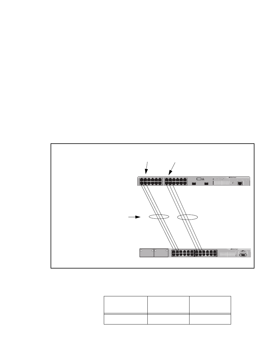
Here are a two examples. Figure 35 illustrates an AT-9400 Series switch
with two LACP trunks, each containing three links. Because both
aggregate trunks go to the same 802.3ad-compliant device, in this case
another Fast Ethernet switch, each trunk requires a separate aggregator.
Figure 35. Example of Multiple Aggregators for Multiple Aggregate Trunks
Here is how the example looks in a table format.
AT-9400 Series Switch
802.3ad-compliant Device
Aggregate Trunks
in Separate Aggregators
Ports 1 - 3
in Aggregator 1
Ports 12 -14
in Aggregator 2
Ethernet Switch
FAULT
RPS
MASTER
POWER
CLASS 1
LASER PRODUCT
STATUS
TERMINAL
PORT
1
3
5
7
9
11
2
4
6
8
10
12
13
15
17
19
21
23R
14
16
18
20
22
24R
AT-9424T/SP
Gigabit Ethernet Switch
1
3
5
7
9
11
13
15
17
19
21
23R
2
4
6
8
10
12
14
16
18
20
22
24R
23
24
L/A
D/C
D/C
L/A
D/C
L/A
1000 LINK / ACT
HDX / COL
FDX
10/100 LINK / ACT
PORT ACTIVITY
L/A
1000 LINK / ACT
SFP
SFP
24
SFP
23
LINK
MODE
LINK
MODE
FAULT
RPS
MASTER
PWR
MODE
STATUS
AT-8524M
Fast Ethernet Switch
Aggregator
Description
Aggregator
Ports
Aggregate
Trunk Ports
Aggregator 1
1-3
1-3