HP OneView User Manual
Page 291
4.
Click Create + to add the FCUS4 uplink set to the Enclosure2LIG logical interconnect group
and reopen the Add uplink set screen.
5.
Add the uplink set for FC 4:
a.
For Name, enter FCUS4.
b.
For Type, select Fibre Channel.
c.
For Network, select FC 4.
d.
Configure the uplink ports. For Interconnect under Uplink Ports, select Interconnect: 2 and
then select ports X3 and X4.
e.
Click Create.
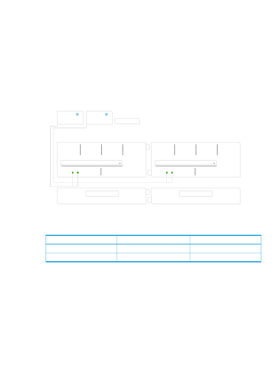
The Create logical interconnect group dialog box opens.
See the following illustration for an example.
Create logical interconnect group
General
V
General
?
Name
Enclosure 2LIG
FCUS3
X
1 network
2 uplink ports
X
1 network
2 uplink ports
FCUS4
Add uplink set
interconnect 1
1
3
2
4
1
2
3
4
Q1
X1 X2 X3 X4 X5 X6 X7 X8
X9 X10
1
2
3
4
Q2
1
2
3
4
Q3
1
2
3
4
Q4
HP VC FlexFabric 20/40 F8 Module
interconnect 2
1
2
3
4
Q1
X1 X2 X3 X4 X5 X6 X7 X8
X9 X10
1
2
3
4
Q2
1
2
3
4
Q3
1
2
3
4
Q4
HP VC FlexFabric 20/40 F8 Module
Create
Create +
Cancel
Logical Interconnect Group
Add Interconnect
Add Interconnect
Creating the uplink sets for the Ethernet networks
You will create the uplink sets for the development and testing networks.
Interconnect port
Uplink set
Networks
Q1.1
devUS
development networks
Q1.2
testUS
test networks
1.
Click Add uplink set.
The Add uplink set screen opens.
2.
Configure the uplink set for the development networks:
a.
For Name, enter devUS.
b.
For Type, select Ethernet.
The dialog box expands to include additional configuration items.
c.
For Connection Mode, select Automatic.
The default value, automatic, instructs the system to determine the best load-balancing
scheme by creating as many LAGs (link aggregation groups) as possible in a physical
interconnect, enabling multiple links to behave as a single link.
d.
For LACP timer, use the default value.
e.
Click Add networks to open the Add Networks to devUS dialog box.
A.5 Provisioning eight host servers for VMware vSphere Auto Deploy
291