IAI America PCON-CF User Manual
Page 97
79
6. Data Entry
6.2.10 Overview of 7-point Type
The number of positioning points is kept small, or specifically to seven or less. This type assumes simple
applications where the PLC ladder sequence only requires a simple circuit configuration.
I/O signals provide separate command inputs and movement complete outputs for respective position numbers.
Accordingly, the signal pattern is different from the one in the 64-point positioning type (PIO pattern = 0).
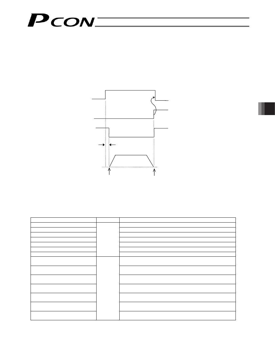
Example) The differences are explained by using an example of moving the actuator to the target position for
position No. 5.
[1] 7-point
type
* In the 64-point type, a position command input (binary) signal and a start input signal must be turned ON at
staggered timings to initiate movement (refer to the next page). In this type, however, there is only one input
signal that needs to be turned ON.
Explanation of I/O signals
Signal name
Category
Function explanation
Direct position command 0 (ST0)
Movement command to the target position for position No. 0
Direct position command 1 (ST1)
Movement command to the target position for position No. 1
Direct position command 2 (ST2)
Movement command to the target position for position No. 2
Direct position command 3 (ST3)
Movement command to the target position for position No. 3
Direct position command 4 (ST4)
Movement command to the target position for position No. 4
Direct position command 5 (ST5)
Movement command to the target position for position No. 5
Direct position command 6 (ST6)
Input
Movement command to the target position for position No. 6
Movement complete 0 (PE0)
Indicates that the actuator reached the target position for
position No. 0.
Movement complete 1 (PE1)
Indicates that the actuator reached the target position for
position No. 1.
Movement complete 2 (PE2)
Indicates that the actuator reached the target position for
position No. 2.
Movement complete 3 (PE3)
Indicates that the actuator reached the target position for
position No. 3.
Movement complete 4 (PE4)
Indicates that the actuator reached the target position for
position No. 4.
Movement complete 5 (PE5)
Indicates that the actuator reached the target position for
position No. 5.
Movement complete 6 (PE6)
Output
Indicates that the actuator reached the target position for
position No. 6.
Combination of dedicated
movement command input
and complete output
Direct position command
5 input (ST5)
Movement complete 5
output (PE5)
Position complete output
(PEND)
No more than 6 msec
Actuator movement
Starting position
of movement
Target position