IAI America PCON-CF User Manual
Page 83
65
5. I/O Signal Control and Signal Functions
Emergency stop (*EMGS)
This signal remains ON while the controller is normal, and will turn OFF if the emergency stop circuit is cut off.
Program the PLC so that it will monitor this signal and implement appropriate safety measures for the entire
system if the signal turns OFF.
Load output judgment status (LOAD)
* This is a dedicated signal available only with the PCON-CF.
If used in a press-fitting application, the controller must be able to know if the specified load threshold was
reached during push & hold operation.
A desired load threshold and check band range are set in the position table, and this signal will turn ON when
the command torque exceeds the threshold while the actuator is inside the check band range.
With the LOAD signal, judgment is made based on whether the total duration of periods in which the command
torque has exceeded the threshold corresponds at least to a specified time. The specific processing procedure is
the same as the one used when determining a completion of push action. The time used for judgment of load
output can be changed freely using user parameter No. 50, “Load output judgment time.”
Torque level status (TRQS)
* This is a dedicated signal available only with the PCON-CF.
If a load threshold is set, this signal will turn ON when the motor current reaches the load threshold while the
actuator is moving.
Since the level of current is monitored, the ON/OFF status of this signal will change when the current changes.
In the weak field-magnet vector control used for stepping motors, the balance of current and torque will be lost
once a specific speed is exceeded. To use the command current to determine if the threshold has been reached,
therefore, the push speed must be limited. Note, however, that the range of permissible push speeds varies
depending on the motor and lead, which means that the push speed set in user parameter No. 34 must also be
adjusted according to the applicable motor and lead.
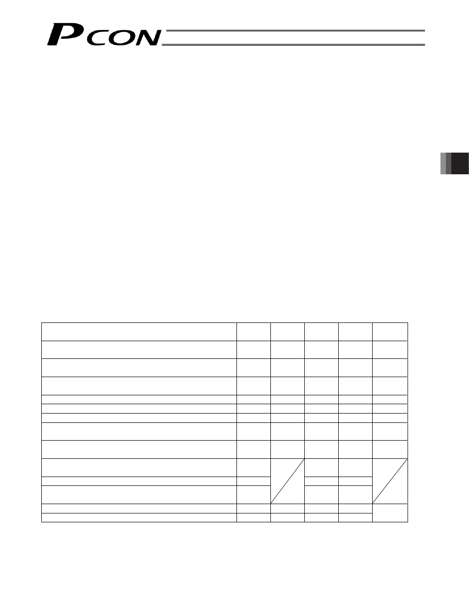
Output Signal Changes in Each Mode
Mode classification
MOVE
PEND
SV
HEND
PM1 ~
PM256
Actuator is stopped with the servo ON after the power
was input
OFF ON ON OFF OFF
Home return is in progress following an input of the
home return signal
ON OFF ON OFF OFF
Home return has completed following an input of the
home return signal
OFF ON ON ON OFF
Actuator is moving in the positioning/push & hold mode
ON
OFF
ON
ON
OFF
Actuator is paused in the positioning/push & hold mode
OFF
OFF
ON
ON
OFF
Positioning has completed in the positioning mode
OFF
ON
ON
ON
ON
Actuator has stopped after contacting the work part in
the push & hold mode
OFF ON ON ON ON
Actuator has stopped after missing the work part (no
work part) in the push & hold mode
OFF OFF ON ON ON
Actuator is stopped with the servo ON in the teaching
mode
OFF ON
ON
Actuator is jogging in the teaching mode
ON
ON
ON
Actuator is being moved by hand with the servo OFF in
the teaching mode
OFF
OFF ON
Servo is OFF after home return
OFF
OFF
OFF
ON
OFF
Emergency stop has been actuated after home return
OFF
OFF
OFF
ON
(Note) Determine whether the actuator has stopped after contacting the work part or missing the work part from
the signal statuses of MOVE, PEND and PM1 to PM256.