Z pio pattern 2 [256-piont mode, 38 4. w iring – IAI America PCON-CF User Manual
Page 56
38
4. W
iring
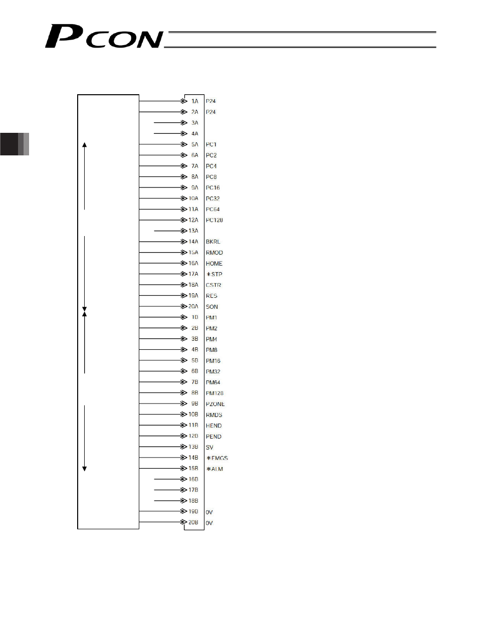
z PIO pattern 2 [256-piont mode]
0 [V]
0 [V]
+24 [V]
+24 [V]
Controller end
PIO (signal abbreviation)
Output s
ide
Command position 1
Command position 2
Command position 4
Command position 8
Command position 16
Command position 32
Command position 64
Command position 128
Brake release
Operating mode
Home return
Pause
Start
Alarm reset
Servo ON
Completed position 1
Completed position 2
Completed position 4
Completed position 8
Completed position 16
Completed position 32
Completed position 64
Completed position 128
Position zone output
Operating mode status
Home return completion
Position complete
Ready
Emergency stop
Alarm
Input si
de
Host system
Brown 1
Red 1
Orange 1
Yellow 1
Green 1
Blue 1
Purple 1
Gray 1
White 1
Black 1
Brown 2
Red 2
Orange 2
Yellow 2
Green 2
Blue 2
Purple 2
Gray 2
White 2
Black 2
Brown 3
Red 3
Orange 3
Yellow 3
Green 3
Blue 3
Purple 3
Gray 3
White 3
Black 3
Brown 4
Red 4
Orange 4
Yellow 4
Green 4
Blue 4
Purple 4
Gray 4
White 4
Black 4
Upper
stage
Lower
stage
(Note) *STP, *ALM and *EMGS are based on the negative logic.
LOAD/TRQS