Z pio pattern 4 [solenoid valve mode 1, 40 4. w iring – IAI America PCON-CF User Manual
Page 58
40
4. W
iring
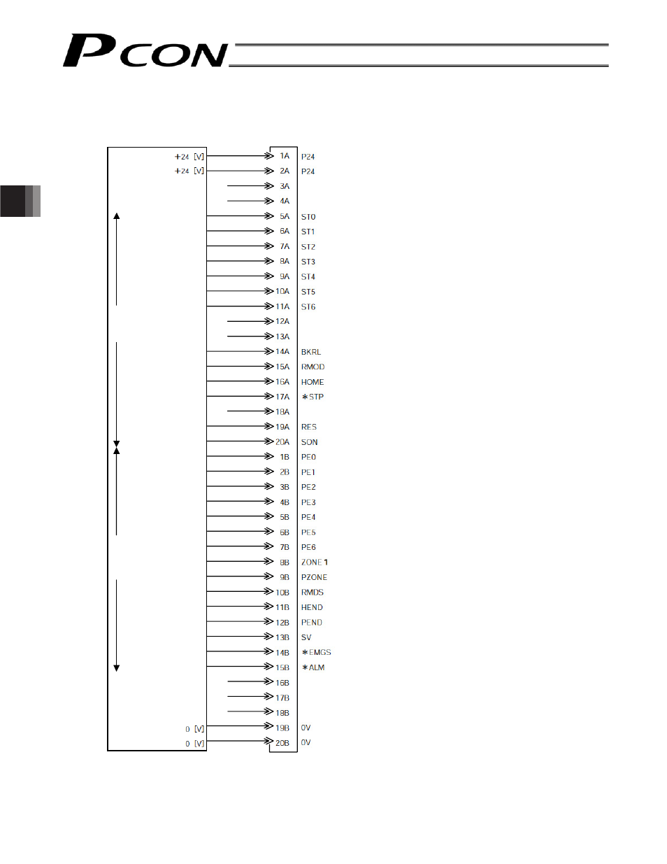
z PIO pattern 4 [Solenoid valve mode 1]
PIO
Direct position command 0
Direct position command 1
Direct position command 2
Direct position command 3
Direct position command 4
Direct position command 5
Direct position command 6
Brake release
Operating mode
Home return
Pause
Alarm reset
Servo ON
Movement complete 0
Movement complete 1
Movement complete 2
Movement complete 3
Movement complete 4
Movement complete 5
Movement complete 6
Zone output
Position zone output
Operating mode status
Home return completion
Position complete
Ready
Emergency stop
Alarm
Host system
Brown 1
Red 1
Orange 1
Yellow 1
Green 1
Blue 1
Purple 1
Gray 1
White 1
Black 1
Brown 2
Red 2
Orange 2
Yellow 2
Green 2
Blue 2
Purple 2
Gray 2
White 2
Black 2
Brown 3
Red 3
Orange 3
Yellow 3
Green 3
Blue 3
Purple 3
Gray 3
White 3
Black 3
Brown 4
Red 4
Orange 4
Yellow 4
Green 4
Blue 4
Purple 4
Gray 4
White 4
Black 4
Upper
stage
Lower
stage
Controller end
(signal abbreviation)
Output s
ide
Input si
de
(Note) *STP, *ALM and *EMGS are based on the negative logic.
LOAD/TRQS