2 sio converter (optional) – IAI America PCON-CF User Manual
Page 166
148
3&7
HDFKLQJ3HQGDQW&RQQHFWLRQ0HWKRGLQ0XOWLD[LV&RQ¿JXUD
WLRQV
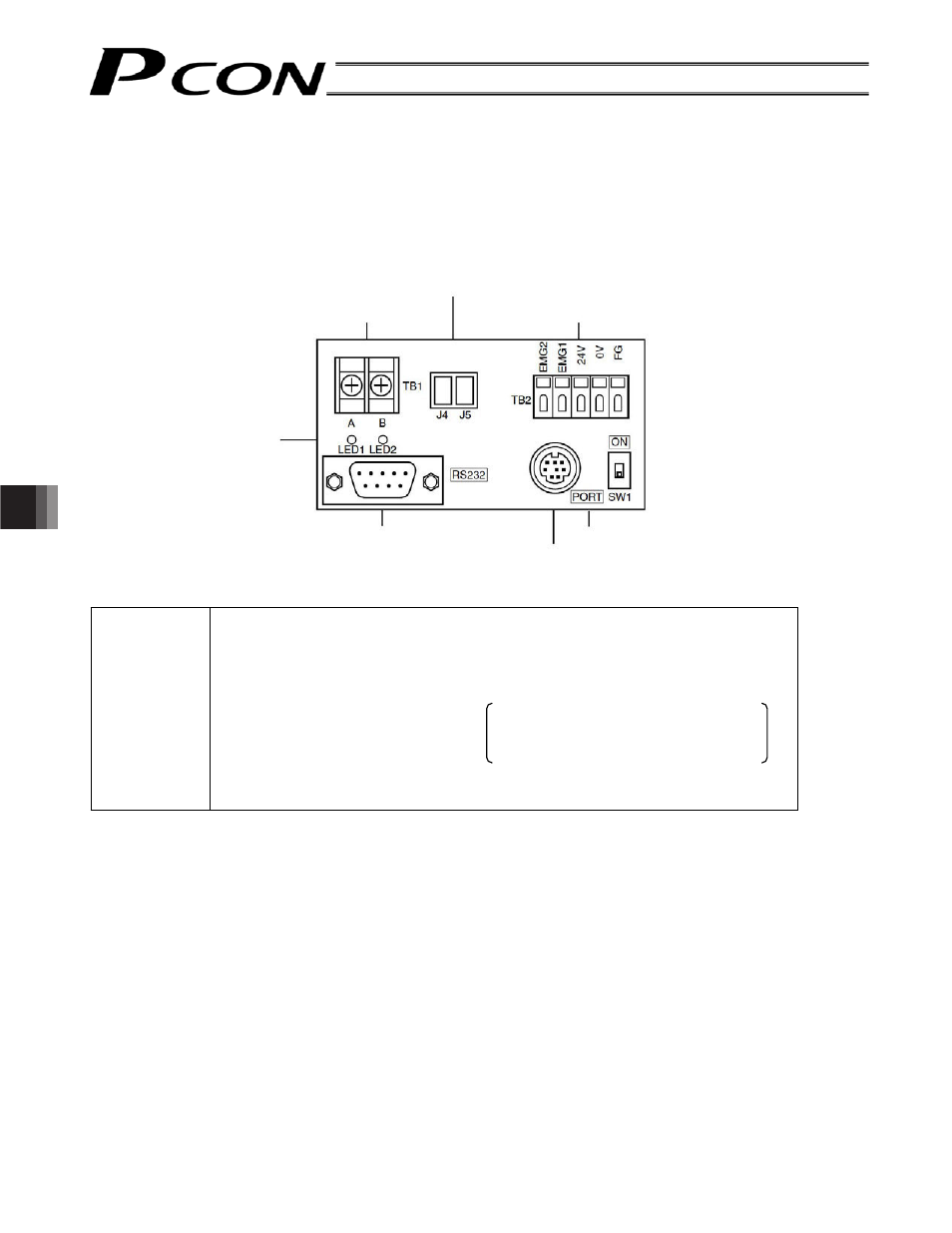
9.2 SIO Converter (Optional)
This unit is a RS232C-RS485 converter.
When multiple controllers are linked, you can connect a teaching pendant to the mini DIN 8-pin connector to
move all axes together or edit the parameters of all axes at once.
z Explanation of function
[1] Power/emergency-stop terminal block (TB2)
EMG1, EMG2
Provide a contact output for the emergency-stop switch on the teaching pendant
(RCM-T/E).
EMG1 and EMG2 connect to the emergency-stop switch on the teaching pendant
when the PORT switch is ON, or are shorted when the PORT switch is OFF.
These terminals comprise an interlock with a safety circuit provided by the user.
24V
Positive side of the 24-V power supply power supply for the teaching pendant
and conversion circuit
Current consumption: 0.1 A max.
0V
Negative side of the 24-V power supply
FG
FG of the 24-V power supply
[2] Link-connection terminal block (TB1)
A connection port for linking the controller.
“A” on the left side connects to SGA (wire color: orange/red 1) on the extension cable.
“B” on the right connects to SGB (wire color: orange/black 1) on the extension cable.
(Note) Be sure to use twisted pair wires for the above two connections (SGA/SGB).
[3] Link connectors (J4, J5)
e-con connector ports for linking controllers. You can connect an optional link cable (CB-RCB-CTL002)
directly to each connector. Take note that J4 and J5 are provided for connection of two axes only. If you
want to connect three or more axes, use the terminal block indicated by [2].
[2] Link-connection terminal block (TB1)
[1] Power/emergency-stop terminal block (TB2)
[7] Monitor LEDs
[4] D-sub, 9-pin connector
[5] Mini DIN, 8-pin connector
[6] PORT switch
[3] Link connectors (J4, J5)