2 explanation of modes – IAI America PCON-CF User Manual
Page 88
70
6. Data Entry
6.1.1
Relationship of Push Force at Standstill and Current-Limiting Value
When performing operation in the push & hold mode, enter the current-limiting value (%) in the push column of
the position-data table.
Determine the current-limiting value (%) from the push force to be applied to the work part at standstill.
For the relationship of push force at standstill and current-limiting value for each actuator type, refer to the
Appendix.
6.2 Explanation of Modes
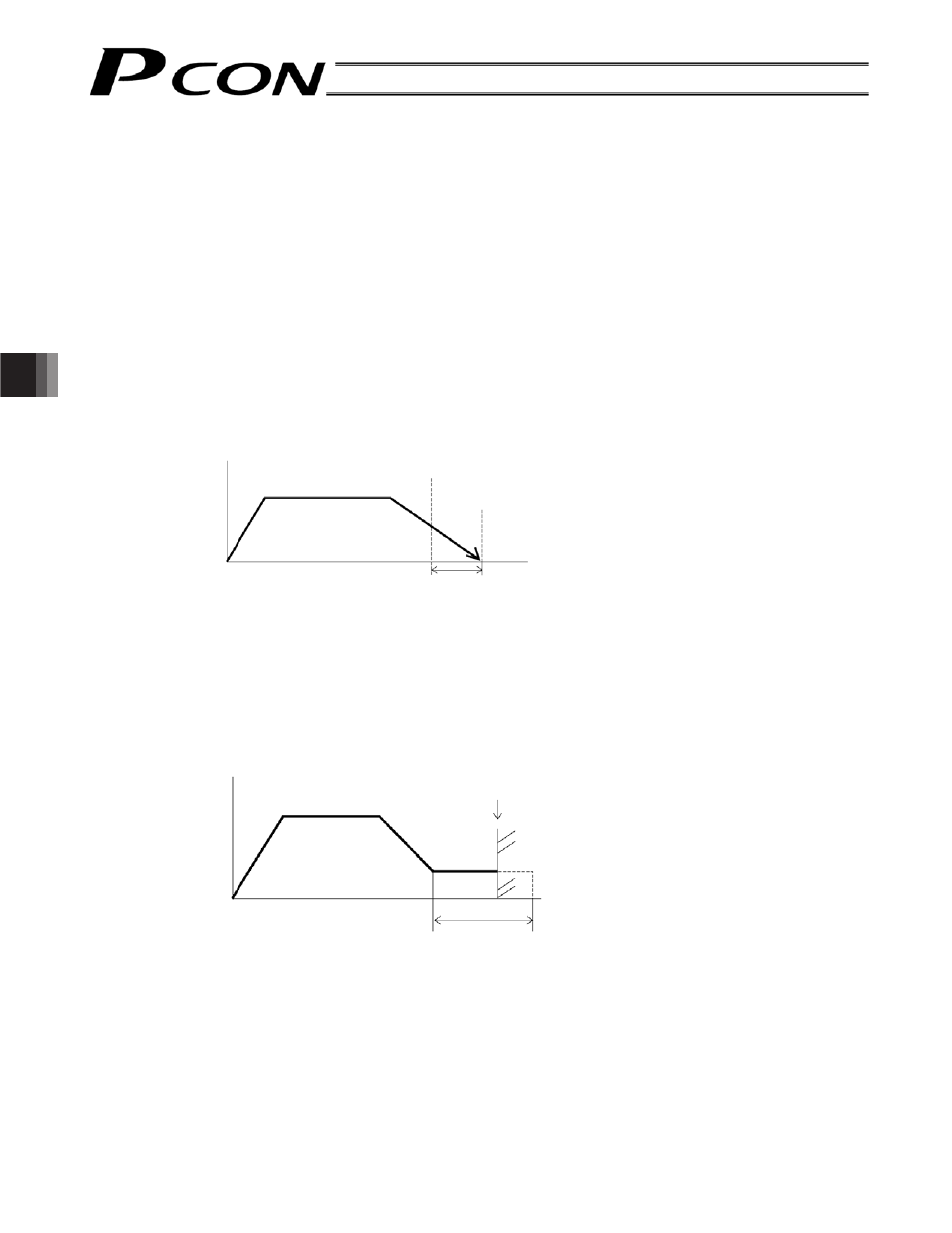
6.2.1 Positioning
Mode
Push = 0
The actuator moves to the target position set in the “Position” field of the position table.
6.2.2
Push & Hold Mode
Push = Other than 0
(1) Work part was contacted successfully
Upon reaching the target position set in the “Position” field of the position table, the actuator moves at the push
speed for the distance set in the “Positioning band” field.
If the actuator contacts the work part while moving and the controller recognizes that “push action has
completed,” the position complete signal will turn ON.
The push speed is set by parameter No. 34.
The factory setting varies with each actuator in accordance with the actuator’s characteristics.
Set an appropriate speed by considering the material and shape of the work part, among others.
Since the maximum speed is 20 mm/s, operate the actuator at a speed not exceeding this value.
Set a positioning band slightly longer than the last position, in order to absorb possible mechanical variation
of the work part.
Speed
Moving distance
Positioning band
Time
Target position
The position complete
signal turns ON here.
Speed
Moving distance
Target position
Positioning band
(maximum push distance)
The position complete signal turns ON here,
as completion of push action is recognized
after the load has been contacted.