2 name and function of each part of the controller – IAI America PCON-CF User Manual
Page 36
18
6SHFL¿FDWLRQV
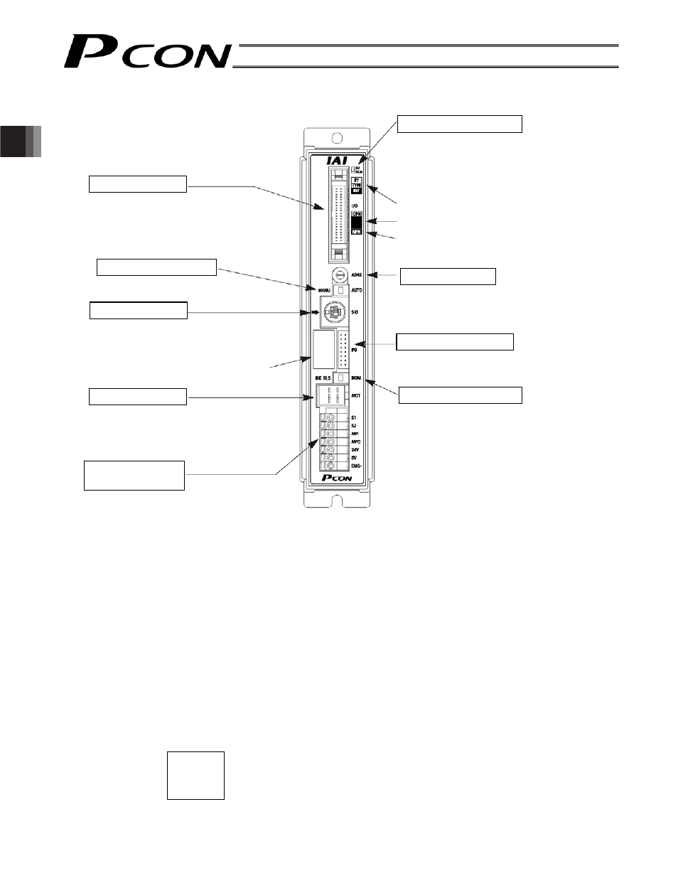
2.2 Name and Function of Each Part of the Controller
Indication of PIO pattern number
If you have multiple systems and a different PIO pattern is used for each system, it is recommended that you
specify an applicable PIO pattern number on each controller to prevent confusion.
Explanation of input/output signal pattern
NPN --- Sink type
PNP --- Source type
Explanation of motor drive-power cutoff circuit
INT --- PCON-C/CF [Internal drive-power cutoff relay type]
EXT --- PCON-CG [External drive-power cutoff relay type]
Indication of model name of actuator to be connected
The type name, ball screw lead length and stroke of the applicable actuator are indicated. When connecting
the cables, check this information to confirm that they are connected to the correct actuator.
Example of indication:
The PIO pattern number is specified here.
The input/output signal pattern is indicated
here.
Motor connector
Encoder connector
Brake release switch
PIO connector
Connects the PLC and PIOs.
Mode selector switch
SIO connector
Connects the teaching
pendant/PC.
Connects the motor cable.
Power-supply
terminal block
Status indicator LEDs
The motor drive-power cutoff
circuit is indicated here.
Connects the encoder cable.
Address switch
The model name of the actuator to
be connected is indicated here.
RA4C
L: 5 mm
ST: 200
m The actuator type is RA4C.
m The ball screw lead length is 5 mm.
m The stroke is 200 mm.
SV (green) --- The servo is on
A blinking green light indicates
that the automatic servo-off
mode is active.
ALM (red) --- An alarm is present.