IAI America PCON-CFA User Manual
Page 50
2.
ACON-C/CG, PCON-C/CG
42
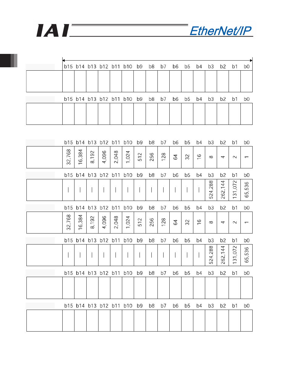
PLC output
Address (* “n” indicates the first output address of each axis.)
When the target position is shown using the negative figure, it is expressed using the complement of 2.
When the zone boundary is shown using the negative figure, it is expressed using the complement of 2.
1 word = 2 bytes =16 bits
Target
position
(lower word)
Target
position
(upper word)
n+2, n+3
n+0, n+1
Positioning
band
(lower word)
Positioning
band
(upper word)
Speed
(lower word)
Zone
boundary +
(lower word)
Speed
(upper word)
Zone
boundary +
(upper word)
n+12, n+13
n+10, n+11
n+8, n+9
n+6, n+7
n+4, n+5
n+14, n+15