IAI America PCON-CFA User Manual
Page 105
3. SCON-CA/CF
A
97
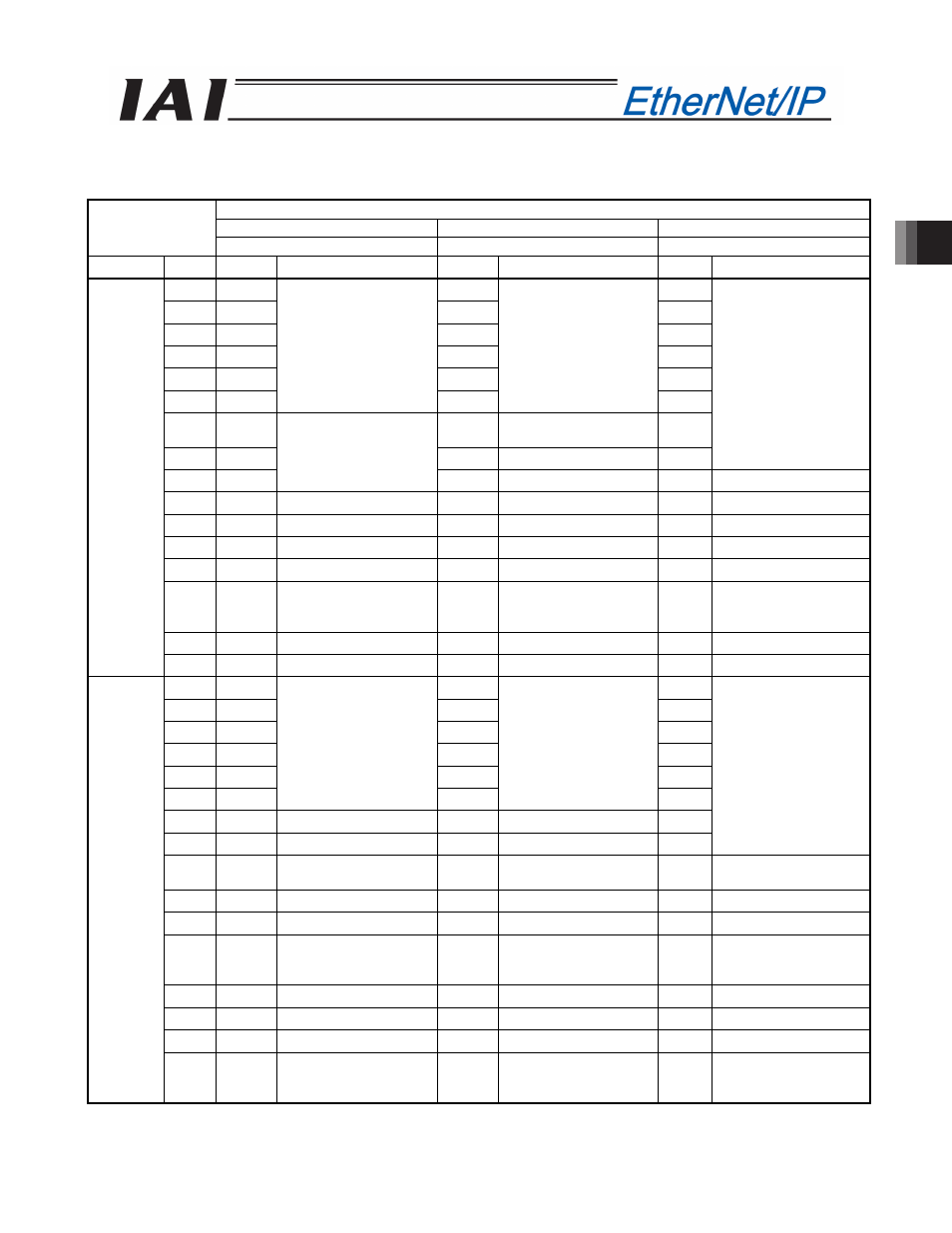
(3) I/O signal assignment
The controller's I/O port signal varies depending on the parameter No. 25 setting.
(Refer to operation manual for the controller main body for more information.)
Parameter No. 25 setting
Positioning mode
Teaching mode
256-point mode
0
1
2
Category Port No. Symbol
Signal name
Symbol
Signal name
Symbol
Signal name
0
PC1
PC1
PC1
1
PC2
PC2
PC2
2
PC4
PC4
PC4
3
PC8
PC8
PC8
4
PC16
PC16
PC16
5
PC32
Command position No.
PC32
Command position No.
PC32
6
-
MODE
Teaching mode
command
PC64
7
-
JISL
Jog/inching selector
PC128
Command position No.
8
-
Unavailable
JOG+
+Jog
-
Unavailable
9
BKRL
Forced brake release
JOG-
-Jog
BKRL Forced brake release
10
RMOD Operating mode selector RMOD Operating mode selector RMOD Operating mode selector
11
HOME
Home return
HOME
Home return
HOME
Home return
12
*STP
Pause
*STP
Pause
*STP
Pause
13
CSTR
Positioning start
CSTR/
PWRT
Positioning
start/position data
import command
CSTR
Positioning start
14
RES
Reset
RES
Reset
RES
Reset
PLC output
o
PCON-
CA/CFA
input
15
SON
Servo ON command
SON
Servo ON command
SON
Servo ON command
0
PM1
PM1
PM1
1
PM2
PM2
PM2
2
PM4
PM4
PM4
3
PM8
PM8
PM8
4
PM16
PM16
PM16
5
PM32
Completed position No.
PM32
Completed position No.
PM32
6
MOVE
Moving signal
MOVE
Moving signal
PM64
7
ZONE1
Zone 1
MODES Teaching mode signal PM128
Completed position No.
8
PZONE/
ZONE2
Position zone/
Zone 2
PZONE/
ZONE1
Position zone/
Zone 1
PZONE/
ZONE1
Position zone/
Zone 1
9
RMDS Operation mode status
RMDS
Operation mode status RMDS Operation mode status
10
HEND Home return completion HEND Home return completion HEND Home return completion
11
PEND Positioning completion
signal
PEND/
WEND
Positioning completion
signal/
position-data read complete
PEND Positioning completion
signal
12
SV
Operation preparation end
SV
Operation preparation end
SV
Operation preparation end
13
*EMGS
Emergency stop
*EMGS
Emergency stop
*EMGS
Emergency stop
14
*ALM
Alarm
*ALM
Alarm
*ALM
Alarm
PCON-
CA/CFA
output
o
PLC input
15
LOAD/
TRQS/
*ALML
Load output judgment/
torque level/
Light error status
*ALML
Light error status
LOAD/
TRQS/
*ALML
Load output judgment/
torque level/
Light error status
The symbol with a * mark shows the ON signal in normal condition.
The signal described as “Unavailable” is not controlled. (ON/OFF is undefined.)