IAI America PCON-CFA User Manual
Page 233
4. SCON-CA
225
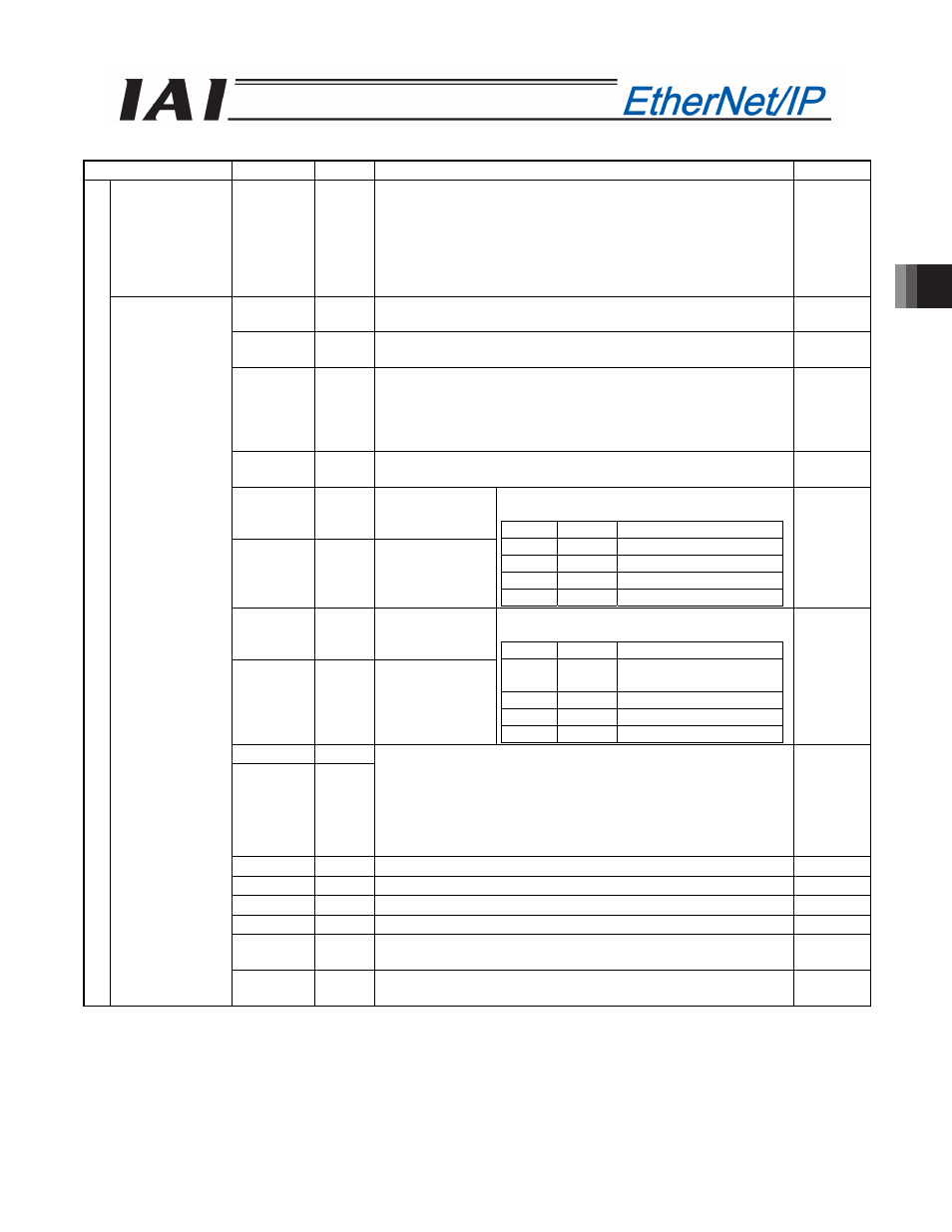
(* “ON” in the table shows the corresponding bit of “1” and “OFF” shows “0”.)
Signal type
Bit
Symbol
Description
Details
Pressing
current-limiting
value
16-bit data
-
16-bit integer.
Specify the current-limiting value during pressing operation.
The specified range is 0 (0%) to 255 (100%).
The actual specifiable range varies with each actuator. (Refer to
the catalog or operation manual for each actuator.)
If a move command is issued by specifying a value exceeding the
maximum pressing current value, an alarm will occur.
4.8 (2)
b15
BKRL Forced brake release: The brake is released when the signal
turns ON.
4.6.11 (18)
b14
RMOD Operation mode: AUTO mode when the signal is OFF, or MANU
mode when the signal is ON.
4.6.11 (19)
b13
DIR
Pressing direction specification:
When the signal is OFF, the direction of the position obtained by
subtracting the positioning band from the target position is used.
When the signal is ON, the direction of the position obtained by
adding the positioning band to the target position is used.
4.6.11 (22)
b12
PUSH Pressing specification: Positioning operation when the signal is
OFF, or pressing operation when the signal is ON.
4.6.11 (21)
b11
GSL1
Servo gain
parameter set
selection 1
b10
GSL0
Servo gain
parameter set
selection 0
Select the servo gain parameter set to be
used.
GSL1
GSL0
Function
OFF
OFF
Select parameter set 0.
OFF
ON
Select parameter set 1.
ON
OFF
Select parameter set 2.
ON
ON
Select parameter set 3.
4.6.11 (33)
b9
NTC1
Vibration
damping control
mode selection 1
b8
NTC0
Vibration
damping control
mode selection 0
Select the vibration damping control
parameter set to be used.
NTC1
NTC0
Function
OFF
OFF
Do not use vibration
damping control.
OFF
ON
Select parameter set 1.
ON
OFF
Select parameter set 2.
ON
ON
Select parameter set 3.
4.6.11 (29)
b7
MOD1
b6
MOD0
Acceleration / deceleration mode:
When both MOD1 and MOD0 are OFF, the trapezoid pattern
mode is selected.
When MOD1 is OFF and MOD0 is ON, the S-motion mode is
selected.
When MOD1 is ON and MOD0 is OFF, the primary delay filter
mode is selected.
4.6.11 (30)
b5
-
Cannot be used.
-
b4
SON Servo ON command: The servo is ON when the signal is ON.
4.6.11 (5)
b3
RES Reset: A reset is performed when the signal turns ON.
4.6.11 (4)
b2
STP Pause: A pause command is issued when the signal turns ON.
4.6.11 (11)
b1
HOME Home return: A home return command is issued when the signal
turns ON.
4.6.11 (6)
P
LC
o
ut
pu
t
Control signal
b0
DSTR Positioning start command: A move command is issued when the
signal turns ON.
4.6.11 (8)