IAI America PCON-CFA User Manual
Page 43
2.
ACON-C/CG, PCON-C/CG
35
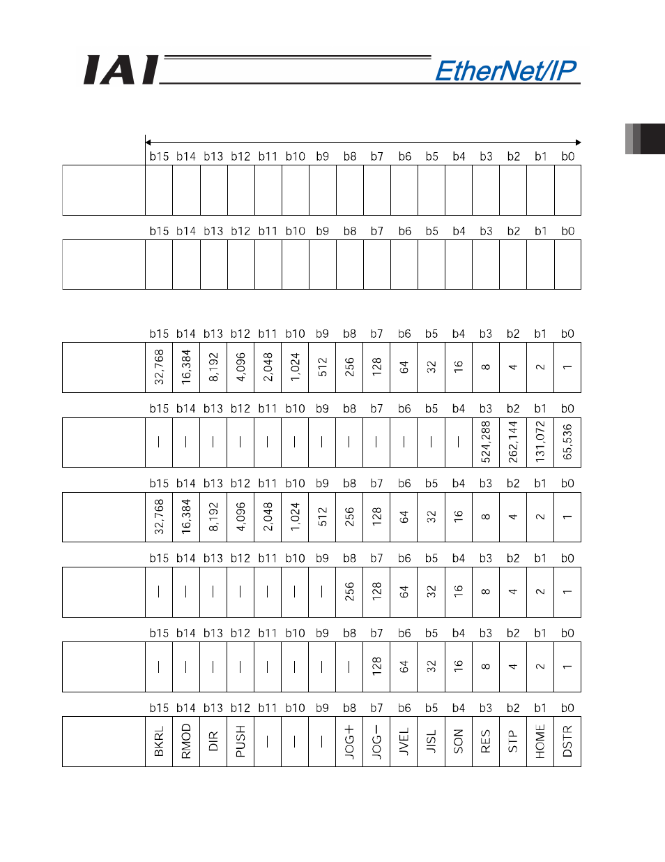
PLC output
Address (* “n” indicates the first output address of each axis.)
When the target position is shown using the negative figure, it is expressed using the complement of 2.
1 word = 2 bytes =16 bits
Target
position
(Lower word)
Target
position
(Upper word)
n+2, n+3
n+0, n+1
Positioning
band
(lower word)
Speed
Acceleration/
deceleration
Pressing
current-limitin
Control signal
Positioning
band
(upper word)
n+12, n+13
n+10, n+11
n+8, n+9
n+6, n+7
n+4, n+5
n+14, n+15