IAI America PCON-CFA User Manual
Page 215
4. SCON-CA
207
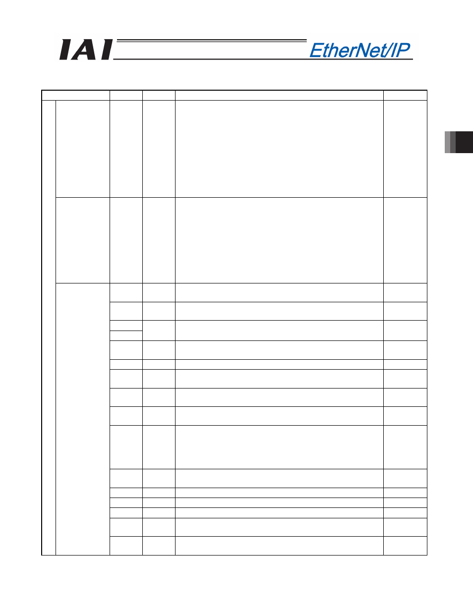
(3) I/O signal assignments(* In the table, ON indicates that the applicable bit is “1,” while OFF indicates that
the applicable bit is “0.”)
Signal type
Bit
Symbol
Description
Details
Target position 32-bit
data
-
32-bit signed integer.
Specify the target position on the absolute coordinates.
The unit is 0.01 mm, while the specifiable range is -999999 to
999999.
(Example) To set +25.40 mm, specify “2540.”
If the entered value exceeds the range of soft limit parameters
(within 0.2 mm inside of the parameter values), the movement
will be limited to within the range of soft limits (within 0.2 mm
inside of the parameter values).
* If this data is entered using a hexadecimal, enter a
negative value as a compliment of 2.
4.8 (1)
Specified
position
number
16-bit
data
PC1 to
PC512
16-bit integer.
To operate the actuator, position data is needed for which
operation conditions have already been entered using the
teaching tools such as PC.
Use this register to specify the position number for which data
has been entered.
The specifiable range is 0 to 767.
If an out-of-range value is specified or the specified position
number is not yet set, an alarm will occur when the start signal
is turned ON.
4.8 (1)
b15
BKRL Forced brake release: The brake is released when the signal
turns ON.
4.6.11 (18)
b14
RMOD Operation mode: AUTO mode when the signal is OFF, or
MANU mode when the signal is ON.
4.6.11 (19)
b13
b12
-
Cannot be used.
-
b11
PMOD Position/simple direct switching: Position mode when the
signal is OFF, or simple direct mode when the signal is ON.
4.6.11 (20)
b10
-
Cannot be used.
-
b9
CLBR Load cell calibration command: Calibration is performed when
this signal turns ON.
4.6.11 (32)
b8
JOG+ +Jog: The actuator moves in the direction opposite home
when the signal is ON.
4.6.11 (13)
b7
JOG- -Jog: The actuator moves in the direction of home when the
signal is ON.
4.6.11 (13)
b6
JVEL
Jog speed/inching distance switching: Parameter No. 26, “Jog
speed” and parameter No. 48, “Inching distance” are used
when the signal is OFF, or parameter No. 47, “Jog speed 2”
and parameter No. 49, “Inching distance 2” are used when the
signal is ON.
4.6.11 (14)
b5
JISL Jog/inching switching: Jog operation when the signal is OFF,
or inching operation when the signal is ON.
4.6.11 (15)
b4
SON Servo ON command: The servo is ON when the signal is ON.
4.6.11 (5)
b3
RES Reset: A reset is performed when the signal turns ON.
4.6.11 (4)
b2
STP Pause: A pause command is issued when the signal turns ON. 4.6.11 (11)
b1
HOME Home return: A home return command is issued when the
signal turns ON.
4.6.11 (6)
PLC
output
Control signal
b0
CSTR Positioning start: A move command is issued when the signal
turns ON.
4.6.11 (7)