IAI America PCON-CFA User Manual
Page 230
4. SCON-CA
222
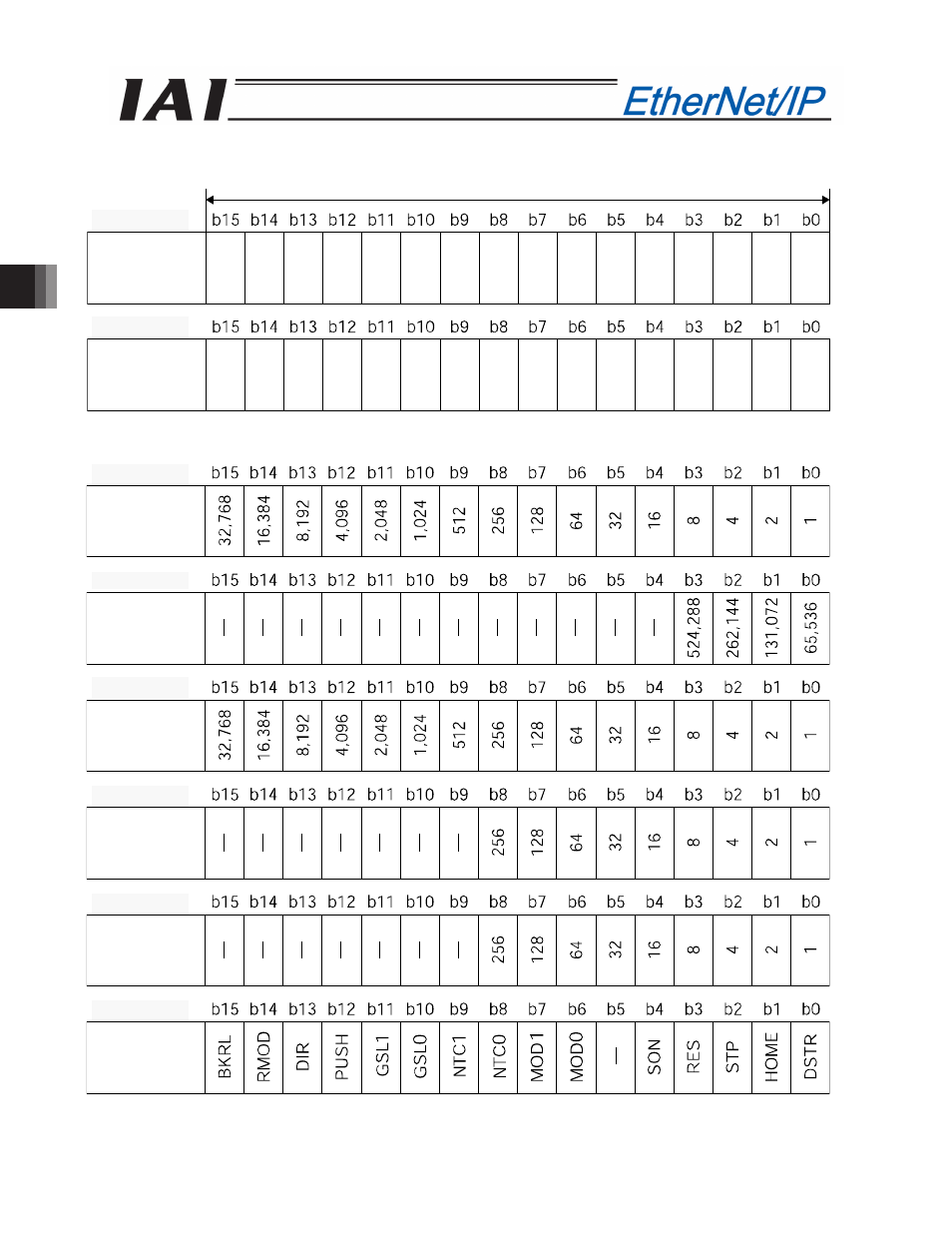
PLC output
Address (* “n” indicates the node address of each axis.)
When the target position is shown using the negative figure, it is expressed using the complement of 2.
Target
position
(lower word)
Target
position
(upper word)
1 word = 2 bytes =16 bits
n+2, n+3
n+0, n+1
Positioning
band
(lower word)
Positioning
band
(upper word)
Speed
Acceleration/
deceleration
Pressing
current-limitin
Control signal
n+13, n+14
n+11, n+12
n+10, n+11
n+8, n+9
n+6, n+7
n+4, n+5