IAI America PCON-CFA User Manual
Page 244
4. SCON-CA
236
(19) Operating mode selector
(RMOD) PLC output signal
Operation Mode Status
(RMDS) PLC input signal
The operation mode is selected with the RMOD signal and the MODE switch located on the front surface of
the controller.
Also, which mode is currently set, AUTO or MANU, can be confirmed using the RMDS signal.
The operation modes with the combination of the RMOD signal and the MODE switch ON/OFF are
described as follows.
Controller MODE
Switch = AUTO
Controller MODE
Switch = MANU
RMOD signal = OFF
(AUTO mode is specified)
AUTO mode
(RMDS=OFF)
MANU mode
(RMDS=ON)
RMOD signal = ON
(MANU mode is specified)
MANU mode
(RMDS=ON)
MANU mode
(RMDS=ON)
(Note) In MANU mode, the startup of the operation from PLC is not available.
(20) Position/simple-direct switching (PMOD) PLC output signal
This signal changes over the use of the value registered in the controller position table for the target
position in the movement and the use of the value specified in the PLC's target position register.
PMOD=OFF: Use the position table
PMOD=ON: Use the value of the target position resister
(21) Pressing specification (PUSH) PLC output signal
When the movement command signal is output after this signal is turned ON, the pressing operation is
performed.
When this signal is set to “OFF”, the normal positioning operation is performed.
(Refer to Item (2) Operation in Half Direct Value Mode in 4.8 “Operation” for the setting timing for this
signal)
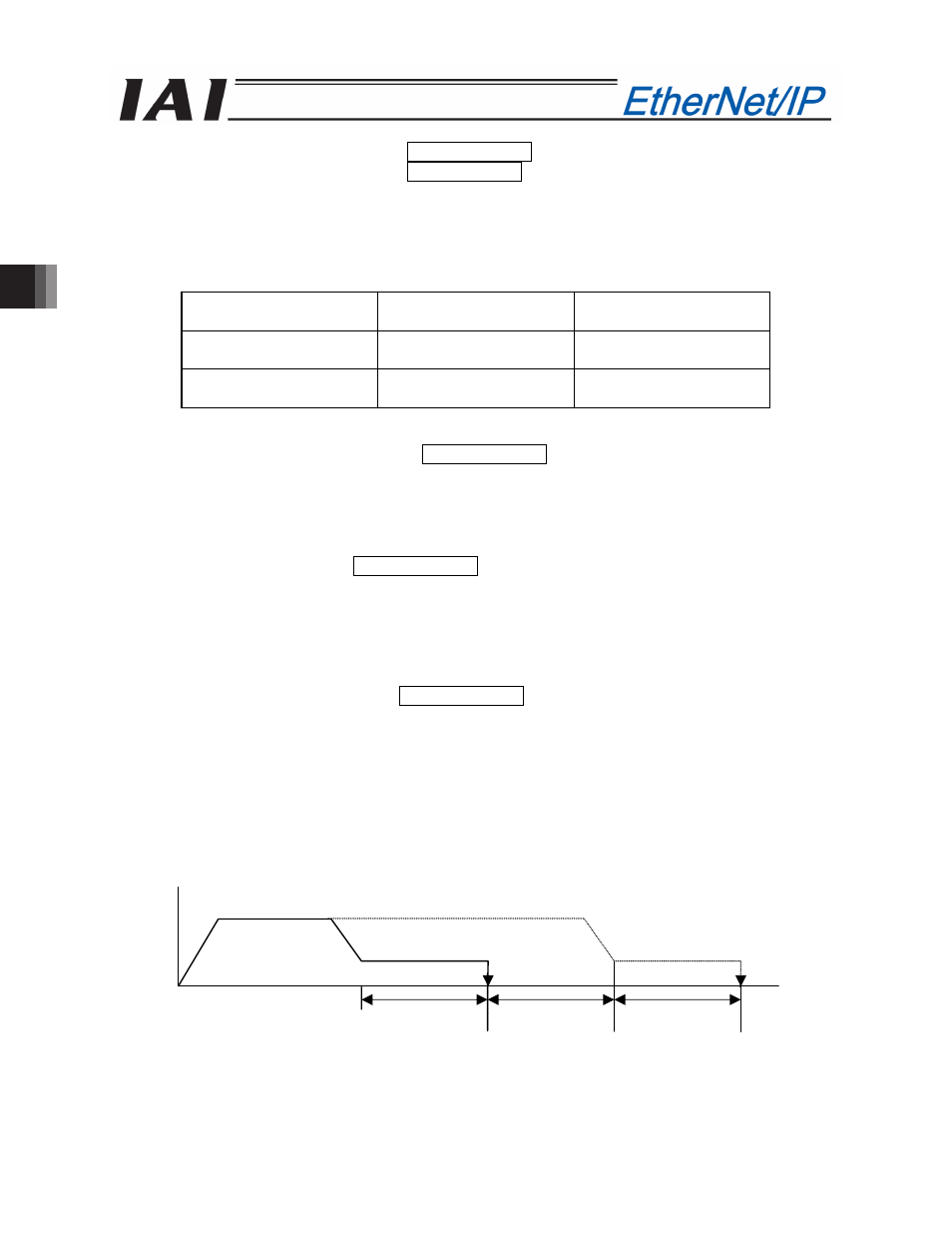
(22) Pressing direction specification (DIR) PLC output signal
This signal specifies the pressing direction.
When this signal is turned “OFF”, the pressing operation is performed to the position expressed using the
value reducing the positioning band from the target position.
When this signal is turned “ON”, the pressing operation is performed to the direction of the value
determined by adding the positioning band to the target position.
In the case of the normal pressing operation, this signal is disabled.
Refer to Item (2) Operation in Half Direct Value Modes 1 to 3 in 4.8 "Operation” for the setting timing for this
signal)
Speed
Travel
Positioning band Positioning band Positioning band
DIR=OFF
Target position
DIR=ON