IAI America PCON-CFA User Manual
Page 113
3. SCON-CA/CF
A
105
(2) I/O signal allocation for each axis
The I/O signals of each axis consist of one input word (8 words = 16 bytes) and one output word in the I/O
areas.
z
The control signals and status signals are ON/OFF signals in units of bit.
z
The target position and current position are expressed using 2-word (32 bits) binary data. The figures
from –999999 to +999999 (Unit: 0.01mm) can be set in PLC. However, set the position data within the
soft stroke range (0 to effective stroke length) for the actuator concerned.
z
Set the positioning band. The positioning band is expressed using 2-word (32 bits) binary data. The
figures from 1 to +999999 (Unit: 0.01mm) can be set in PLC.
z
The specified speed is expressed using 1-word (16 bits) binary data. The figures from 0 to +65535 (Unit:
1.0mm/sec or 0.1mm/sec) can be set in PLC. Set the value that does not exceed the max. speed value
for the actuator in question.
The unit can be established in Parameter No. 159 FB Half Direct Mode Speed Unit.
Parameter No.159 Setting Value
Indicated Speed Unit
0
1.0mm/sec
1
0.1mm/sec
z
The Acceleration/deceleration is expressed using 1-word (16 bits) binary data. The figures from 1 to 300
(Unit: 0.01G) can be set in PLC. However, set the value that does not exceed the max.
acceleration/deceleration value for the actuator in question.
z
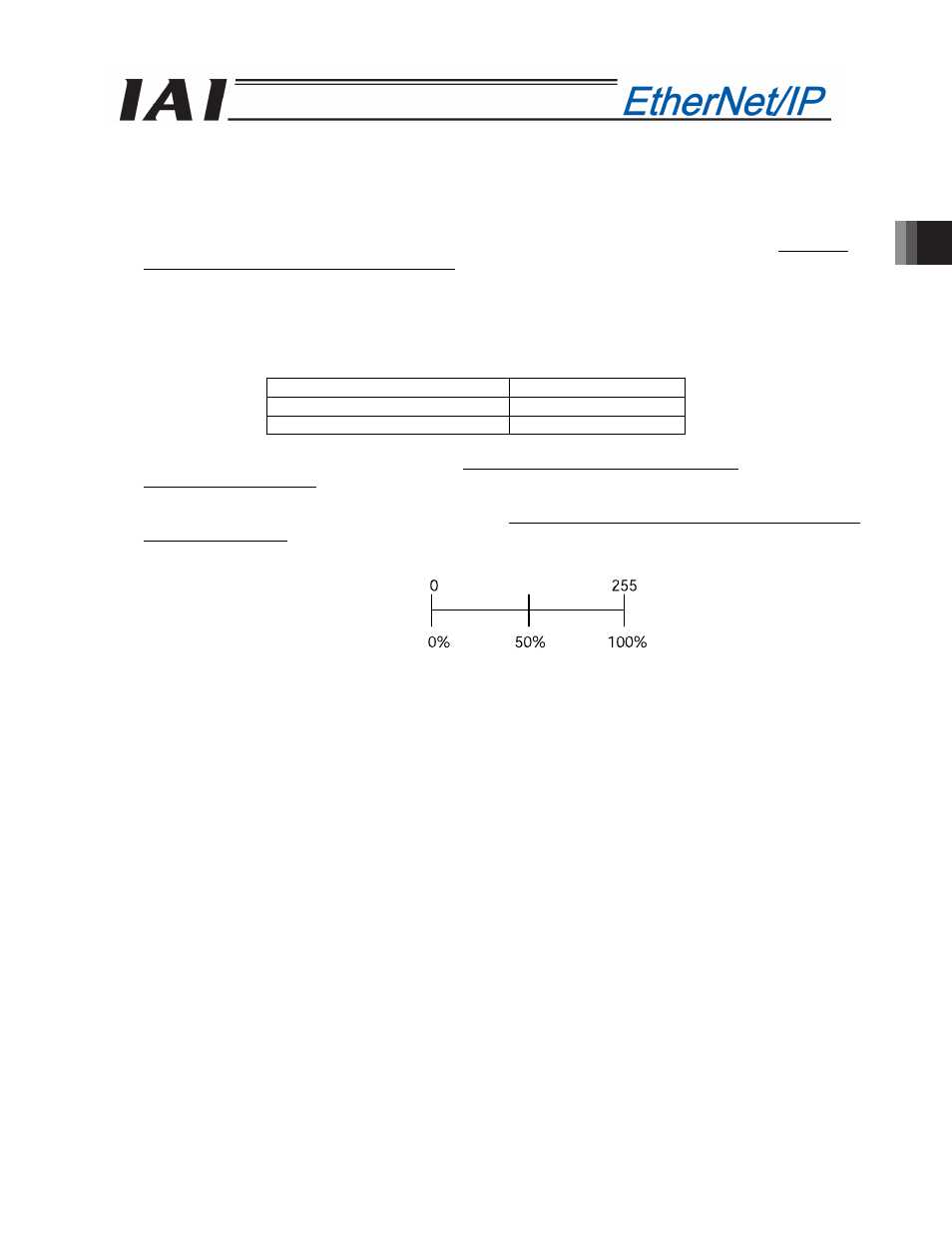
The pressing current-limiting value is expressed using 1-word (16 bits) binary data. The figures from 0
(0%) to 255 (100%) can be set in PLC. However, set the value within the settable range for the pressing
current-limiting value (Refer to the Catalog or operation manual for the actuator) for the actuator
concerned.
Set value
Pressing current-limiting value
z
The command current is expressed using 2-word (32 bits) binary data (Unit: 1mA).
z
The current speed is expressed using 2-word (32 bits) binary data (Unit: 0.01mm/sec).
z
The alarm code is expressed using 1-word (16 bits) binary data.
127