IAI America PCON-CFA User Manual
Page 185
4. SCON-CA
177
4.6.3
Position/Simplified Direct Value Mode (Number of Occupied Bytes: 8)
This is the operation mode with the position No. set up. Whether the target position is set directly the control
signals (PMOD signals), or the value registered on the position data is used can be selected.
For the speed, acceleration/deceleration and positioning band, etc., except for the target position, the
values in the position table within the controller are used. Setup the position data referring the operation
manual for the controller main body.
The settable No. of position data items is max 768 points.
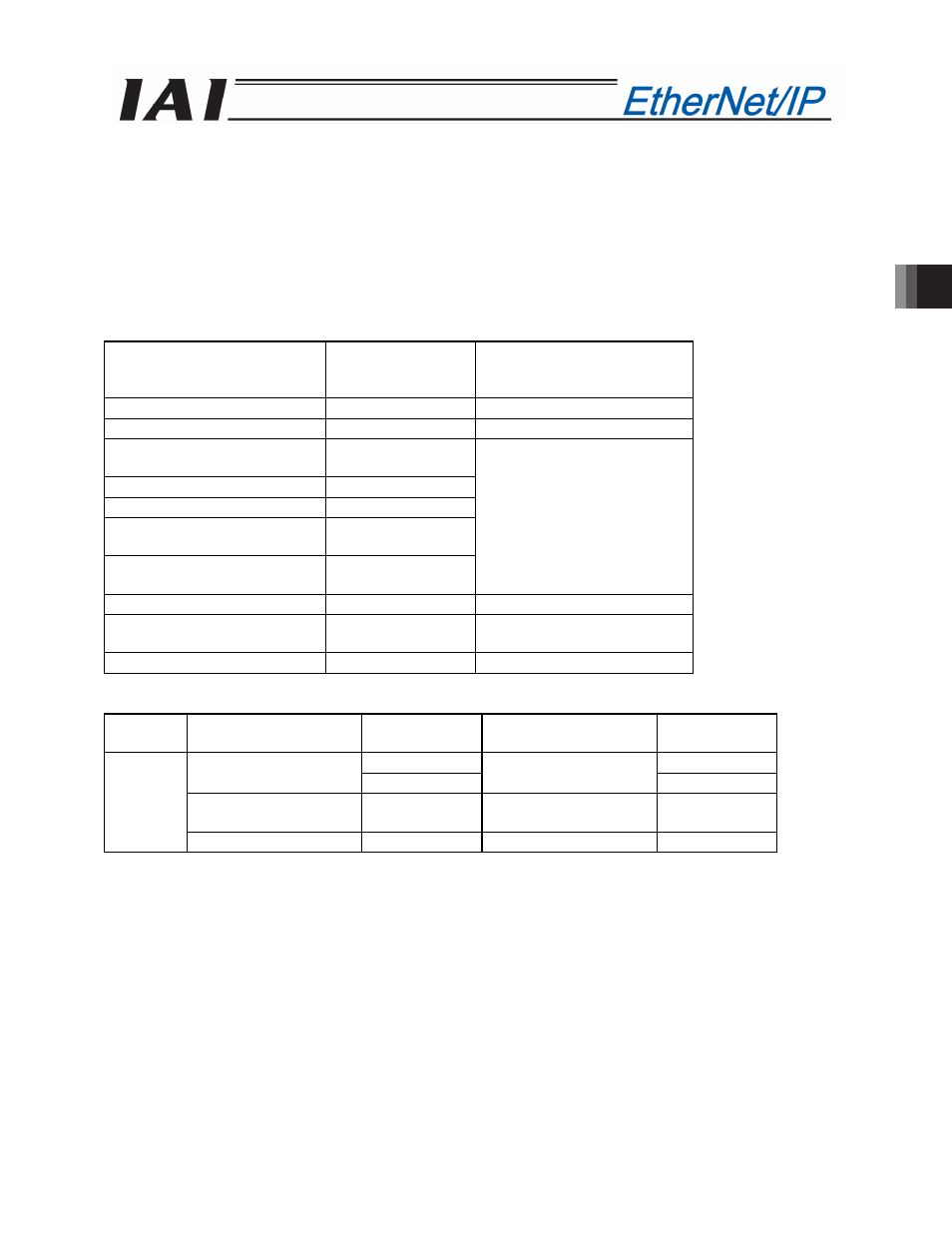
The robot cylinder's effective main functions that can be controlled using this mode, are as shown in the
following table.
ROBO cylinder function
{
: Direct control
U
: Indirect control
x: Disable
Remarks
Home-return operation
{
Positioning operation
{
Speed and acceleration /
deceleration setting
U
Pitch feed (inching)
U
Pressing Operation
U
Speed change during the
movement
U
Operation at different
acceleration and deceleration
U
These items must be set in
the position data table.
Pause
{
Zone signal output
U
Zones are set using position
data or parameters.
PIO pattern selection
x
(1) PLC address configuration (* “n” indicates the node address of each axis.)
Parameter
No.84
SCON-CA side
input register
PLC side output
address (bytes)
SCON-CA side
output register
PLC side input
address (bytes)
n+0, n+1
n+0, n+1
Target position
n+2, n+3
Current position
n+2, n+3
Specified position
number
n+4, n+5
Completed position No.
(Simple alarm code)
n+4, n+5
1
Control signal
n+6, n+7
Status signal
n+6, n+7
(Note) Be careful of using duplicated node addresses.