14 display errors, Display errors – B&K Precision 9171-9174 - Manual User Manual
Page 93
81
(0) is 0 V. To set an output pin’s logic level, use the
GPIO remote
command. Again, all pins (except pin 5) are represented as 8-bits
binary, according to Table 5 above. When using the
GPIO command,
the decimal representation of the 8-bits binary is used.
Taking the example above with pins 8, 6, and 3 set as
OUTPUT pins,
if pins 8 and 3 are to be set with logic high (5 V) and pin 6 set with
logic low (0 V), send the following command:
GPIO 68
68 is used to represent 01000100 in binary. Only pins 8 and 3 have
the value “
1” to represent logic high and output 5 V. Pin 6 has the
value “
0” to represent logic low and output 0 V. All other pins should
be “
0” as they are input pins and thus, are ignored.
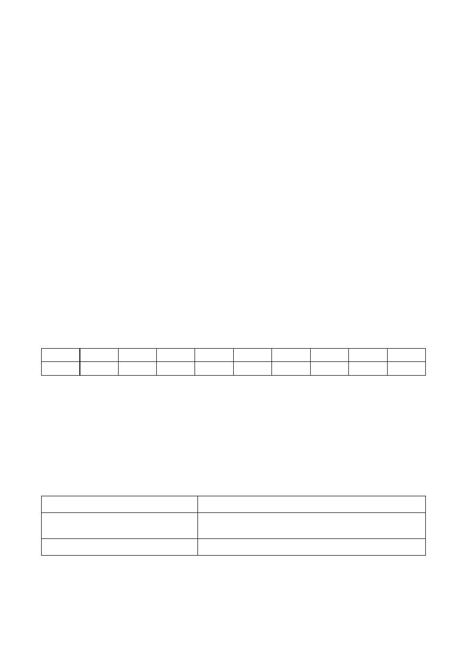
Pin
9
8
7
6
5
4
3
2
1
0
1
0
0
-
0
1
0
0
3.14
Display Errors
The following errors may be displayed under certain operating
conditions. Their descriptions are shown in the tablebelow.
Error Message
Description
INPUT RANGE ERROR!
The input value is out of the settable range
of the power supply.
TURN OFF OUTPUT FIRST Disable output first before accessing menu.