B&K Precision 9171-9174 - Manual User Manual
Page 90
78
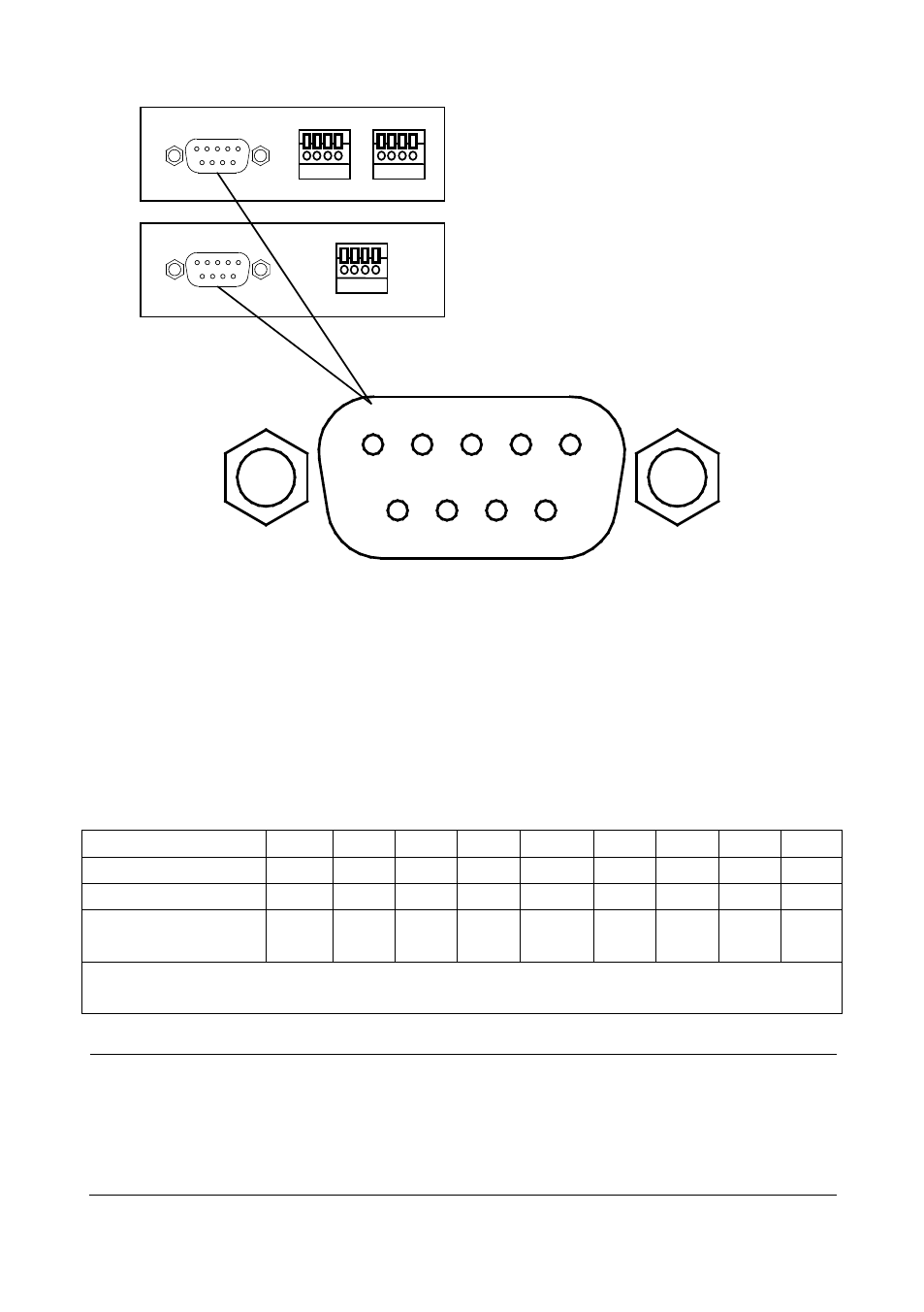
Below are the pin assignments for each of the 9 pins.
Table 5- Digital I/O Pin Assignment
Pin#
9
8
7
6
5
4
3
2
1
Type
I/O I/O I/O I/O GND I/O I/O I/O I/O
Binary Bit #
7
6
5
4
-
3
2
1
0
Decimal
Representation 128 64
32
16
8
4
2
1
I/O – Can be set to either input or output.
GND – Ground pin
WARNING:
Do not input more than 5 V to any of the digital I/O pins.
Doing so may damage the instrument and void its
warranty.
Dual Channel DIO/Analog Card
Single Channel DIO/Analog Card
1
2
3
4
5
6
7
8
9
Figure 25- Digital I/O Interface
This manual is related to the following products: