Table 92 switch sw1, Table 93 switch sw2, Table 94 switch sw3 – Nortel Networks NN43001-301 User Manual
Page 263: Switch sw1 - dchi configuration, Switch sw2 - carrier impedance configuration, Switch sw3 - clock controller configuration, Switch sw4 - carrier shield grounding
Install the NTAK79 PRI card
263
Set the switches on the circuit card according to the requirements of your
specific installation:
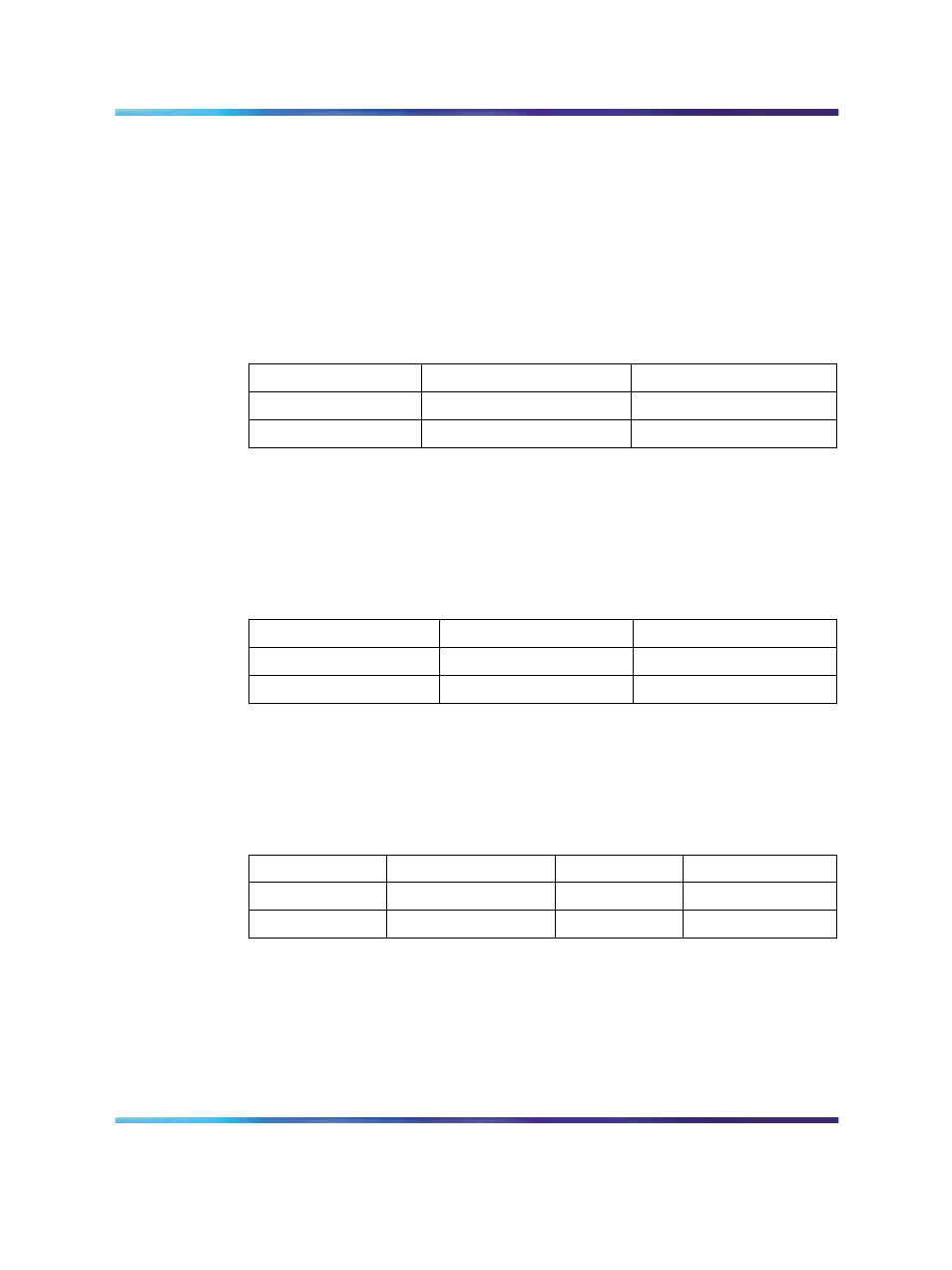
Switch SW1 - DCHI configuration
This switch enables and disables the onboard DCHI and sets the operating
mode of the DCHI.
For the U.K., use DPNSS1 mode. For all other countries, use Q.931 mode.
Table 92
Switch SW1
Switch
Down (On)
Up (Off)
SW 1-1
enable DCHI
disable DCHI
SW 1-2
DPNSS1/DASS2
Q.931
Switch SW2 - Carrier impedance configuration
This switch sets the carrier impedance to either 120
1
/
2
or 75
1
/
2
. Twisted pair
cable is usually associated with 120
1
/
2
. Coaxial cable is usually associated
with the 75
1
/
2
setting.
Table 93
Switch SW2
Cable Type
SW 2-1
SW 2-2
75
1
/
2
Up (Off)
Down (On)
120
1
/
2
Down (On)
Up (Off)
Switch SW3 - Clock controller configuration
This switch enables and hardware disables the onboard Clock Controller.
SW 3-2 should be disabled if the onboard clock controller is not in use.
Table 94
Switch SW3
Switch
Down (On)
Up (Off)
Note
SW 3-1
—
—
Spare
SW 3-2
Disabled
Enabled
Switch SW4 - Carrier shield grounding
This switch allows for the selective grounding of the Tx/Rx pairs of the
carrier cable. Closing the switch (down position) applies Frame Ground
(FGND) to the coaxial carrier cable shield, creating a 75
1
/
2
unbalanced
configuration. This applies only to the NTBK05CA cable.
Nortel Communication Server 1000
ISDN Primary Rate Interface Installation and Commissioning
NN43001-301
02.03
Standard
Release 5.5
7 December 2007
Copyright © 2003-2007, Nortel Networks
.