Ntak10 2.0 mb dti card, Install dti hardware, Figure 82 2.0 mb dti cabling – Nortel Networks NN43001-301 User Manual
Page 238
238
2.0 Mb DTI implementation
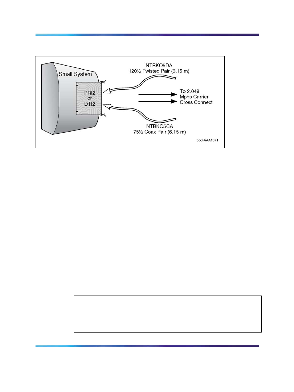
Figure 82
2.0 Mb DTI cabling
NTAK10 2.0 Mb DTI card
The 2.0 Mb DTI card provides the physical interface for the digital E-1
carrier on the system. The card includes an onboard clock controller and is
installed in slots 1 through 9 in the Option 11C Cabinet. On IP Expansion
cabinets, it is placed in slots 11-19, 21-29, 31-39, 41-49 of the first, second,
third, and fourth expansion cabinets, respectively.
The NTAK10 2.0 Mb DTI card is also used for ISL shared mode applications.
For information on the NTAK10 faceplate LEDs, refer to ISDN Primary Rate
Interface Maintenance (NN43001-717).
Install DTI hardware
The NTAK10 circuit card is installed in card slot 1-9 in the Option 11C
Cabinet. On IP Expansion cabinets, it is installed in slots 11-19, 21-29,
31-39, 41-49 of the first, second, third, and fourth expansion cabinets,
respectively.
It is not supported in the Media Gateway Expansion. Up to four digital trunk
cards are supported in each Media Gateway. The NTAK10 card is installed
in Slots 1, 2, 3 and 4 of the Media Gateway.
ATTENTION
IMPORTANT!
Each Media Gateway that has a digital trunk must have a clock controller set to
an external reference clock.
Nortel Communication Server 1000
ISDN Primary Rate Interface Installation and Commissioning
NN43001-301
02.03
Standard
Release 5.5
7 December 2007
Copyright © 2003-2007, Nortel Networks
.