Figure 78, Insert/remove the ntrb21 tmdi card – Nortel Networks NN43001-301 User Manual
Page 204
204
1.5 Mb PRI implementation
4
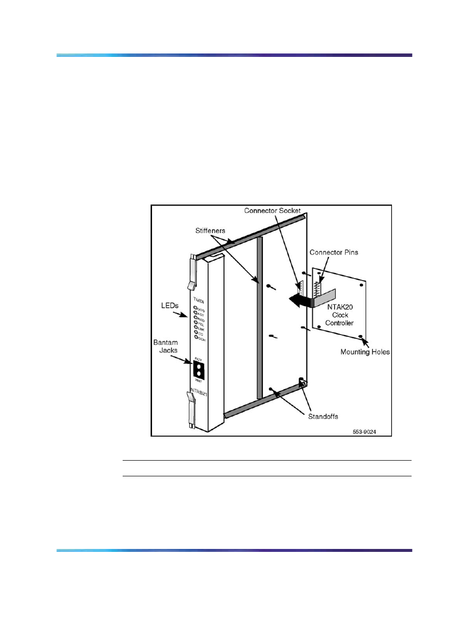
Slowly lower the daughterboard towards the NTRB21, keeping the
standoffs in line with all four holes, until the holes are resting on the
tops of the four standoffs.
If more than a very slight amount of pressure is required at this point,
the connector pins cannot be aligned with the connector socket. If
so, lift the daughterboard off the NTRB21 and return to step 2.
5
Gently apply pressure along the edge of the board where the
connector is located until the standoffs at the two corners adjacent
to the connector snap into a locked position. Then press down on
the two corners on the opposite side until they also lock into place.
Figure 78
NTAK20 daughterboard installation on the NTRB21
—End—
Insert/remove the NTRB21 TMDI card
Refer to
Table 74 "Shelf slot assignments for NTRB21, NTAK09, and
to determine the slot assignment for the NTRB21
TMDI circuit card appropriate to the system.
Nortel Communication Server 1000
ISDN Primary Rate Interface Installation and Commissioning
NN43001-301
02.03
Standard
Release 5.5
7 December 2007
Copyright © 2003-2007, Nortel Networks
.