Table 49 receiver interface switches for nt5d97ad, Table 50 trunk 1 switches, Table 51 ring ground switch for nt5d97ad – Nortel Networks NN43001-301 User Manual
Page 137: Table 50 "trunk, Table 49 "receiver interface
NT5D97AD DIP switch settings
137
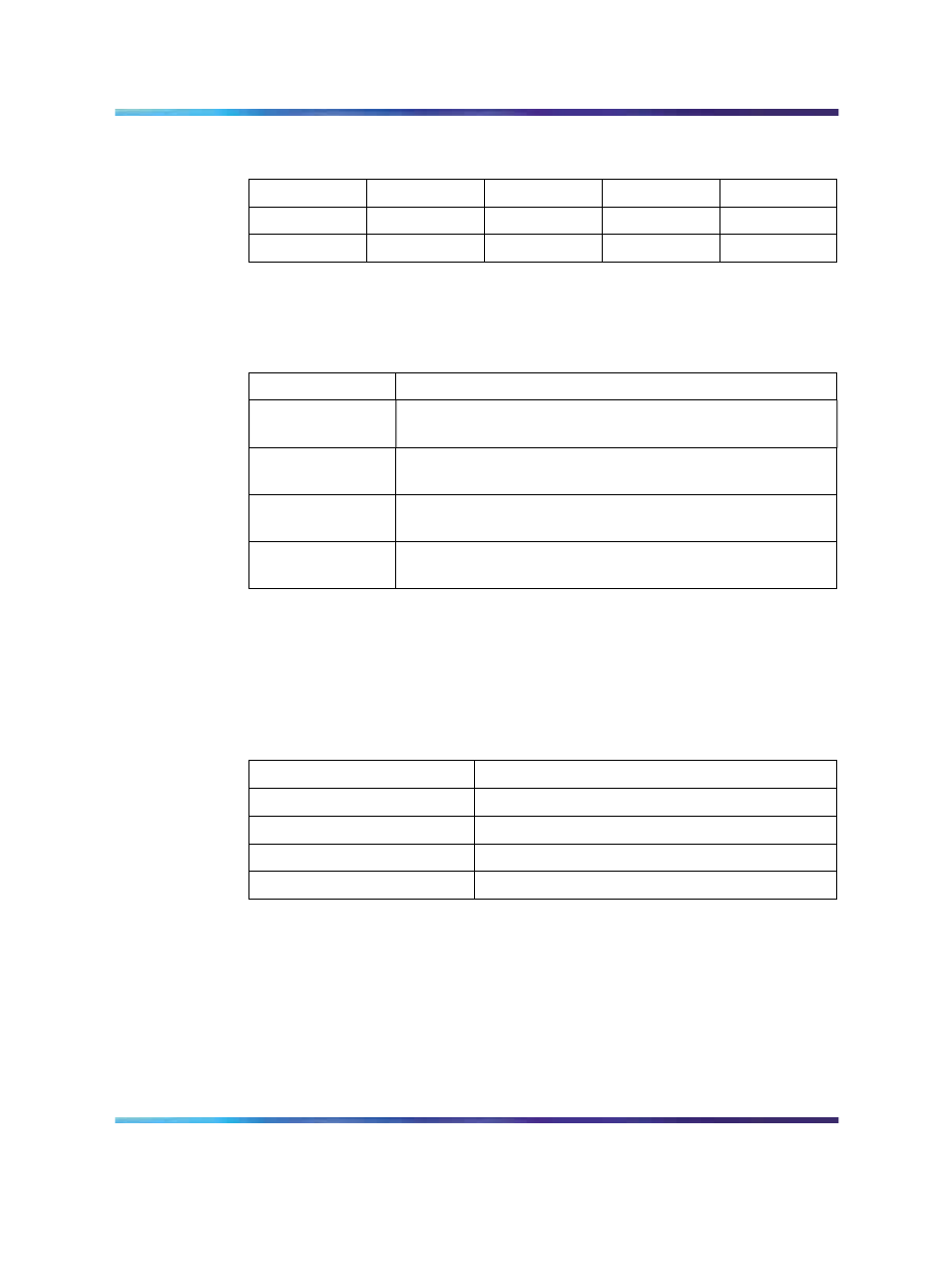
Table 49
Receiver interface switches for NT5D97AD
Impedance
S6-1
S6-2
S6-3
S6-4
75 ohm
OFF
OFF
ON
OFF
120 ohm
OFF
OFF
OFF
ON
Trunk 1 switches for NT5D97AD
Table 50
Trunk 1 switches
Switch
Function
S7
General Purpose...See
switches for NT5D97AD" (page 136)
S10
TX Mode...See
Table 47 "TX mode switches for NT5D97AD"
S13, S14 & S15
LBO...See
Table 48 "LBO switches for NT5D97AD" (page
S11
RX Impedance...See
Table 49 "Receiver interface switches
Ring ground switches for NT5D97AD
Switch S16 selects which ring lines connect to ground. When set to ON,
the ring line is grounded as shown in
Table 51 "Ring ground switch for
.
Table 51
Ring ground switch for NT5D97AD
Switch
Line
S16_1
Trunk 0 Transmit
S16_2
Trunk 0 Receive
S16_3
Trunk 1 Transmit
S16_4
Trunk 1 Receive
DCH Address select switch for NTBK51AA daughter board for
NT5D97AD
Switch S9 selects the NTBK51AA DCH daughterboard address.
Switch S8 is not used when the NTBK51AA daughterboard is used.
S8_1-10 can be set to OFF position as in
switches for NT5D97AD" (page 138)
Nortel Communication Server 1000
ISDN Primary Rate Interface Installation and Commissioning
NN43001-301
02.03
Standard
Release 5.5
7 December 2007
Copyright © 2003-2007, Nortel Networks
.