Figure 83 ntak79 with switch locations, Inspect the ntak79 circuit card, Set the switches on the ntak79 – Nortel Networks NN43001-301 User Manual
Page 262
262
2.0 Mb PRI implementation
Each step is described in the pages that follow. The PRI hardware
installation procedure is the same regardless of the type of system at the
far-end that is, another system such as the AXE-10, or SYS-12.
Inspect the NTAK79 circuit card
•
Locate the NTAK79 2.0 Mb circuit card and carefully remove it from its
packaging.
•
Inspect the circuit card for any visible damage that occurred during
shipping.
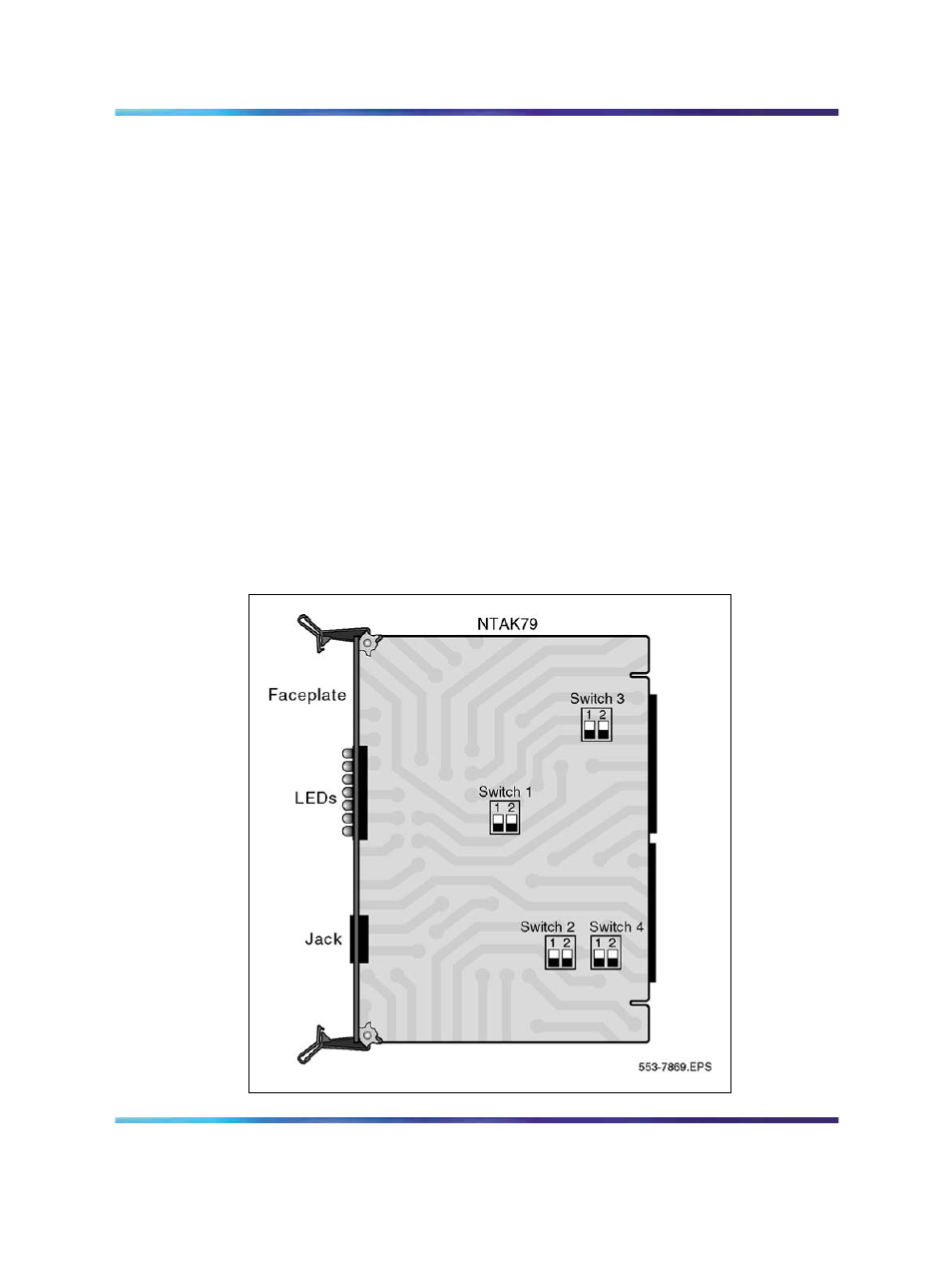
Set the switches on the NTAK79
The NTAK79 incorporates four onboard dip switches. The tables that follow
provide information on the various settings and related functions of these
switches.
Note: The ON position for all the switches is positioned toward the
bottom of the card. This is indicated by a white dot printed on the board
adjacent to the bottom left corner of each individual switch.
Figure 83
NTAK79 with switch locations
Nortel Communication Server 1000
ISDN Primary Rate Interface Installation and Commissioning
NN43001-301
02.03
Standard
Release 5.5
7 December 2007
Copyright © 2003-2007, Nortel Networks
.