Table, Table 67, Table 66 "clock controller – Nortel Networks NN43001-301 User Manual
Page 170
170
Clock Controller description and installation
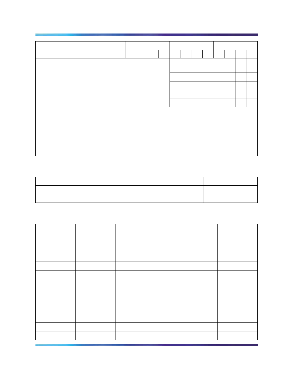
SW1
SW2
SW4
System
1
2
3
4
1
2
3
4
1
2
3
4
*Cable length between the
J3 faceplate connectors:
0–4.3 m (0–14 ft)
off
off
4.6–6.1 m (15–20 ft)
off
on
6.4–10.1 m (21–33 ft)
on
off
10.4–15.2 m (34–50 ft)
on
on
*
If there is only one clock controller card in the system, set to OFF. If there are two clock
controller cards, determine the total cable length between the J3 connectors (no single cable
can exceed 25 ft.) and set these two switch positions for this cable length, as shown above. The
maximum total (combined) length is 50 ft. Set the switches on both cards to the same settings.
**
Set to ON for clock controller 0. Set to OFF for clock controller 1.
Note: FNF based-systems the total clock path length is equal to the length of the NTRC49 cable
used to connect between the two clock controller cards.
Table 66
Clock Controller switch settings for QPC775
System
SW2
SW3
SW4
Half Group, Single Group
ON
OFF
ON
Multi Group
OFF
OFF
ON
Table 67
Clock Controller switch settings for NTRB53
Multigroup/
Single group
Machine
Type # 1
Faceplate
Cable Length
(CC to CC)
Side Number
Machine
Type #2
1
2
3
4
5
6
Multigroup
= Off
Single group =
On
61, 51C, 61C
71, 81, 81C
= On
Off
Off
0-14 ft
Side 0 = On
Side 1 = Off
81 = Off
51, 51C
61, 61C, 81C =
On
Off
On
15-20 ft
On
Off
21-33 ft
On
On
34-50 ft
Nortel Communication Server 1000
ISDN Primary Rate Interface Installation and Commissioning
NN43001-301
02.03
Standard
Release 5.5
7 December 2007
Copyright © 2003-2007, Nortel Networks
.