ATL Telecom R1-SW Ethernet Switch User Manual
Page 100
R1-SW24L2B User’s Manual
5-32
The following example displays sample traceroute output when a destination host IP
address is specified:
# traceroute 61.107.97.51
traceroute to 61.107.97.51 (61.107.97.51), 30 hops max, 40 byte packets
n
1
2
3
172.26.1.254 (172.26.1.254)
192.168.11.126 (192.168.11.126)
61.107.97.51 (61.107.97.51)
14.812 ms 29.758 ms 22.752 ms
0.497 ms 0.454 ms 0.360 ms
14.812 ms 29.758 ms 22.752 ms
o
p
q
#
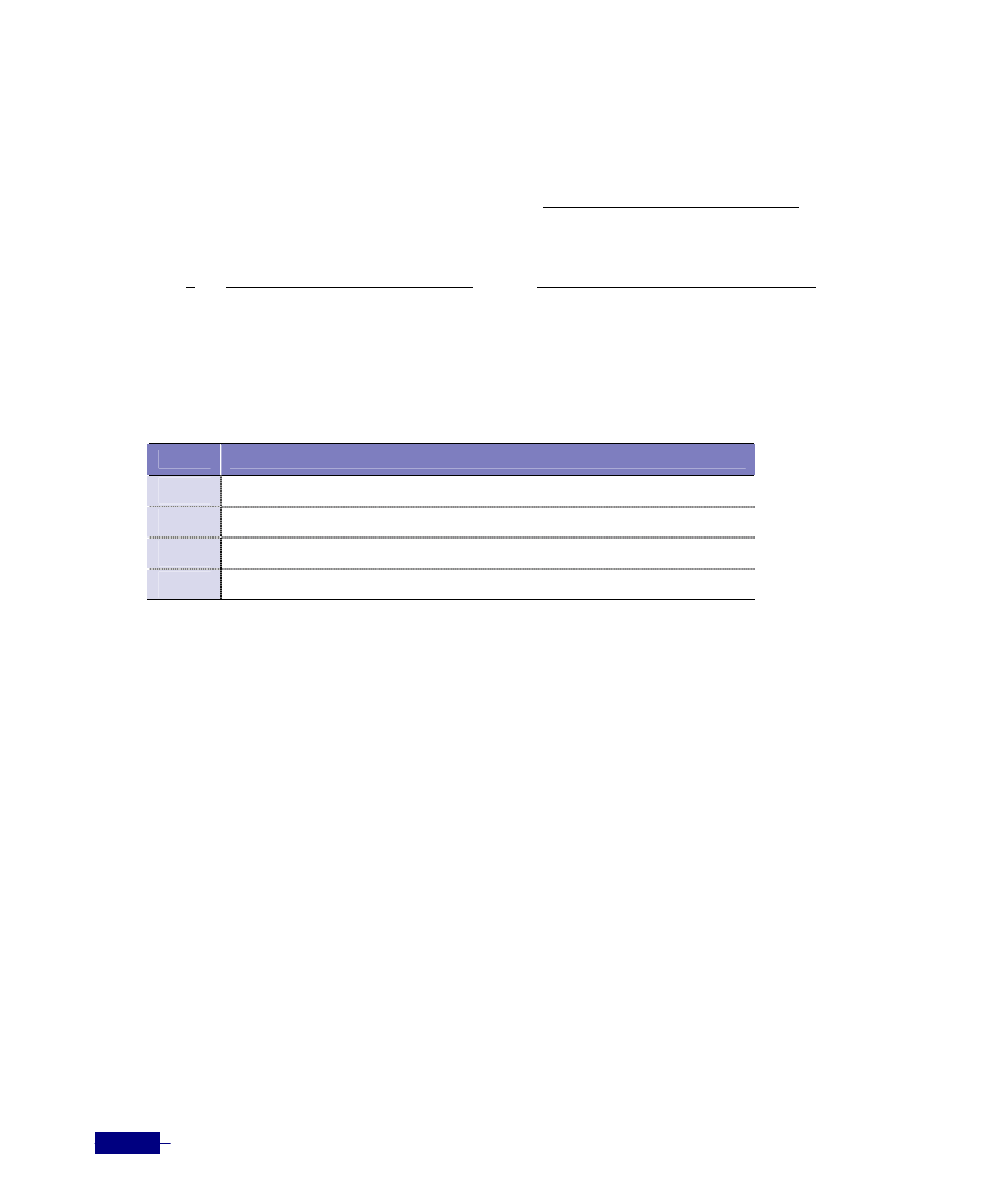
The table below describes the fields shown by the traceroute command:
Table 5-21 traceroute field descriptions
Field
Description
n
Maximum TTL value and the size of the ICMP datagrams being sent
o
Indicates the sequence number of the switch router in the path to the host
p
IP address of the router
q
Round-trip time for each of the three probes that are sent
The following example shows how to display the interface information of the using the show
interface management
command:
# show interface vlan id 1
Interface management
index 0 kernel index 2 metric 1 mtu 1514
HWaddr: 00:11:a1:ca:00:01
inet 172.19.3.154/16 broadcast 172.19.255.255
input packets 1715511, bytes 159585565, dropped 0, multicast packets 0
input errors 0, length 0, overrun 0, CRC 0, frame 0, fifo 0, missed 0
output packets 436568, bytes 54251015, dropped 0
output errors 0, aborted 0, carrier 0, fifo 0, heartbeat 0, window 0
collisions 0
#